Ford Smart Charging Issue (Fixed)
- mrracer98
-
 Topic Author
- Offline
- New Member
-

- Posts: 5
- Thank you received: 3
Car was running, gauges went bonkers, batt light was on. She called local shop, they found the battery fried (had gotten overcharged) they put a new battery in to get it started drove it 3 blocks to their shop. They replaced the alternator, took it for a spin and fried another battery and the new alternator. So they replaced the PCM, due to overcharging, with a junkyard one that ford dealership programmed along with another battery and alternator. (I also see a new starter on it as well, not sure the reason for that). They gave it a clean bill of health and she drove it about 50 miles and now the battery light came back on she brought it back, they either did nothing or replaced the alternator again (we're not sure). So it has had 2-3 batteries and alternators and a different PCM.
SO, I offered to take a look at it, grabbed a multi-meter and checked to see if it was overcharging (safe to drive it), and it was not charging at all... So I drove it to home. By the time I got it home battery was about 11.8 v.
It was not charging and had a P0622 in it. I also note a new batt. sense wire running to the 3 prong plug on the alternator. I did some basic resistance checks (i know kinda pointless) on the GENMON and GENCOM wires from disconnected PCM to disconnected alternator plug and found no resistance to speak of. When I reconnected the battery neg post back on after plugging in the PCM.... it started charging again. urgh, the dreaded intermittent.
I have read these threads:
www.scannerdanner.com/forum/post-your-re...-ford-500-p0622.html
www.scannerdanner.com/forum/diagnostic-t...ernator-testing.html
www.scannerdanner.com/forum/post-your-re...rt-charge-issue.html
I have also watched Erik O SMA video linked in one of these videos.
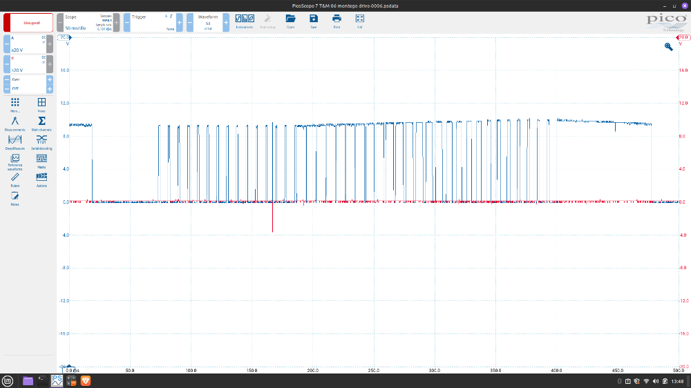
Here is a poorly captured screen shot from my basic PICO. The BLUE trace is the GENMON, RED is GENCON.
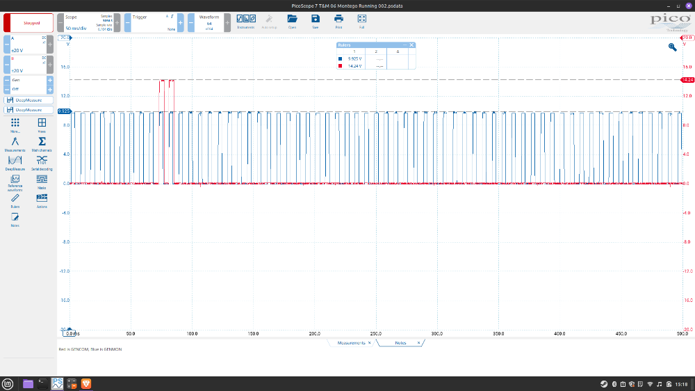
This seems capture to be pretty normal to my untrained eye.
2 things I note, when I add a bunch of electronic loads it appears the alternator cannot quite keep up, its desired voltage is say 14.2 but im only getting 12.3-12.6 ish. Also I note the GENMON line is only around 9.5 volts on the peaks, and I see the other captures in one of those threads listed above as well as the SMA video seem to show the GENMON is a pulsed battery voltage or close to it.
I have checked and the battery sense wire at alternator is good ( KOEO, lights 2 amp test light). Voltage regulator terminals to alternator casing pass ohm's specs listed in service data. I have NOT done PCM power and ground checks yet for voltage drops.
I am concerned based on the above listed ford escape case study thread that this may be an issue of aftermarket alternator (poor voltage regulator). That escape thread is a very similar situation all together. I do not know what alternator is currently in it but highly doubt its a motocraft based on this shop being an auto value place. I could be wrong, but the alternator is so hard to get at, I dont know how to look without removing it, which I may have to do.
Questions:
1) I assume GENMON is a pulsed PWM from the voltage regulator, is this correct?
2) is it safe to assume this GENMON PWM should be at or near battery voltage on the high end of the trace?
3) Any other advice is welcomed.
Please Log in or Create an account to join the conversation.
- mrracer98
-
Topic Author
- Offline
- New Member
-
- Posts: 5
- Thank you received: 3
Please Log in or Create an account to join the conversation.
- Tyler
-

- Offline
- Moderator
-

- Full time HACK since 2012
- Posts: 6126
- Thank you received: 1542
I assume GENMON is a pulsed PWM from the voltage regulator, is this correct?
Correct! The PCM provides voltage on the GENMON line, and the alternator pulses it to ground as a load indicator.
is it safe to assume this GENMON PWM should be at or near battery voltage on the high end of the trace?
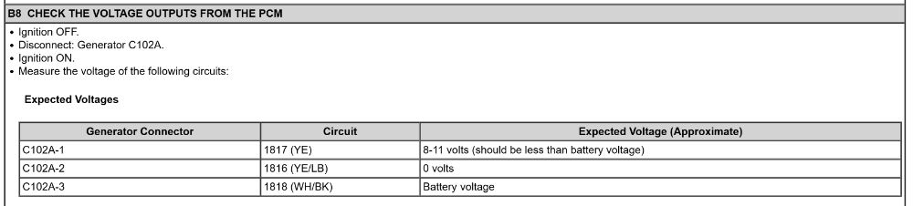
Probably? I tend to think the (nearly) 10V you saw on your GENMON is enough amplitude to create a satisfactory signal for the PCM. Plus, your resistance check on GENMON passed. This part of Pinpoint B from service info seems to think 8-11V is OK:
I think the answer would be to monitor the GENMON PID in scan data. If you're seeing a pulse width signal with the Pico, but the GENMON PID either says 0% or 100%, then there's a problem. If the GENMON PID agrees with the signal you're seeing, don't sweat the amplitude and move on.
Any other advice is welcomed.
Have you voltage dropped the main alternator B+ cable and the case ground? All loads on, preferably while the alternator is struggling to hit the desired voltage. 300 mV would be fine for either. Did you say that you checked that? Apologies if you did.
How hacked in is the new battery sense wire? I'd be tempted to remove it and repair whatever harness damage is there while you're there. Any spread pins in the alternator connector? Techs tend to get desperate after the third alternator and start front probing connectors...
Besides that, I'd be tempted to go with the reman Motorcraft.
Please Log in or Create an account to join the conversation.
- mrracer98
-
Topic Author
- Offline
- New Member
-
- Posts: 5
- Thank you received: 3
Probably? I tend to think the (nearly) 10V you saw on your GENMON is enough amplitude to create a satisfactory signal for the PCM. Plus, your resistance check on GENMON passed. This part of Pinpoint B from service info seems to think 8-11V is OK:
I did start going through that pinpoint B testing procedure, I assumed that 8-11 volts was the bias on that wire, as with the alternator connector unplugged the GENMON reads 8.75 and will not light a test light.
Have you voltage dropped the main alternator B+ cable and the case ground? All loads on, preferably while the alternator is struggling to hit the desired voltage. 300 mV would be fine for either. Did you say that you checked that? Apologies if you did.
My post was not that clear, I did NOT voltage drop the alternator yet. I need to check the sense wire and the B+ cable along with the ground. Sounds like the fusible links are often bad in these, and I do believe it probably had a high voltage event when this all started.
How hacked in is the new battery sense wire? I'd be tempted to remove it and repair whatever harness damage is there while you're there. Any spread pins in the alternator connector? Techs tend to get desperate after the third alternator and start front probing connectors...
I too want to look at this wire, but if it passes a voltage drop I will leave it till last, as they have it running under that smart junction fuse box and I am scared to open a pandoras box due to the MN pus crusties from salt... hopefully it wont come to that. I will verify tomorrow if the fuse still cuts power to it and also voltage drop it.
All good stuff, thank you! I will be checking this over more in the morning.
Please Log in or Create an account to join the conversation.
- mrracer98
-
Topic Author
- Offline
- New Member
-
- Posts: 5
- Thank you received: 3
Well, everything I can think of has checked out so far.
B+ to alternator output =250 mV voltage drop
B+ to voltage sense wire to generator= 87 mV voltage drop, and it is tied into the battery junction box fuse as it should.
Battery Negative to generator housing= 55 mV voltage drop.
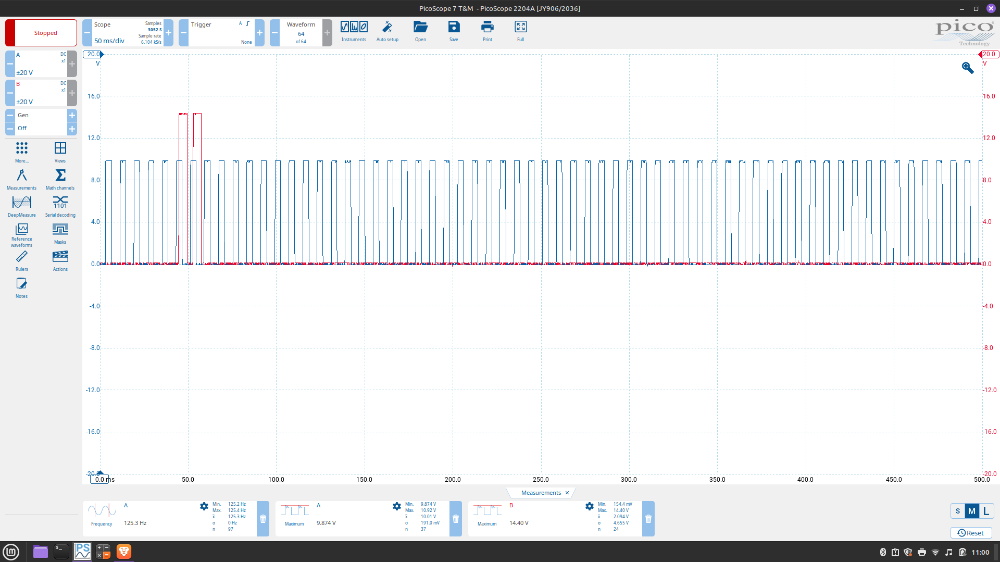
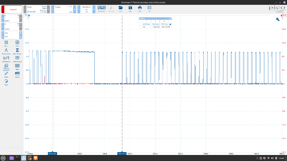
Frequency of the PWM is 125 hz
All this was done under load and at idle. I believe the fusible links and wire integrity is good at this point.
I also shorted the GENMON and GENCON wires together with a 10a fused jumper and they mirrored each other as they should. The only thing I noticed again is when tied together both are maxing out around that 9 volts. Where as when it is running the GENCON is 12 v and the GEN MON is 9 ish volts. I dont know if that means anything, probably not.
(PIcs get degraded for some reason, this was mirroring itself at 166 htz)
Tomorrow I will be putting on some miles on this to try and reproduce the concern. I talked with the lady again today she states it seemed to have a consistent studder, miss, or low power event shortly before the battery light would come on. So I have the vehicle wired up with the pico and will see what I can find out....
Maybe it needs spark plugs??? LOL (See Ivan's video below, CRAZY)
I did NOT get time before work to check computer grounds and powers yet. I will keep this updated as I learn more. If anyone has any further experience or advise please chime in. Thank you I am sure appreciative.
Please Log in or Create an account to join the conversation.
- Farseer
-

- Offline
- Senior Member
-

- Posts: 40
- Thank you received: 5
If the V is normal then, you can rule out a bad second alternator.
Also, doesn't the ECU monitor things like the battery T sensor/or on some cases sensor on B negative? Maybe those inputs are acting up?
Also, out of curiosity, what tells the ECU how many accessories are on? Does it have some sort of V sensing circuit that adds up all the loads so the ECU? Or is that what the sensor on the negative post does?
Please Log in or Create an account to join the conversation.
- mrracer98
-
Topic Author
- Offline
- New Member
-
- Posts: 5
- Thank you received: 3
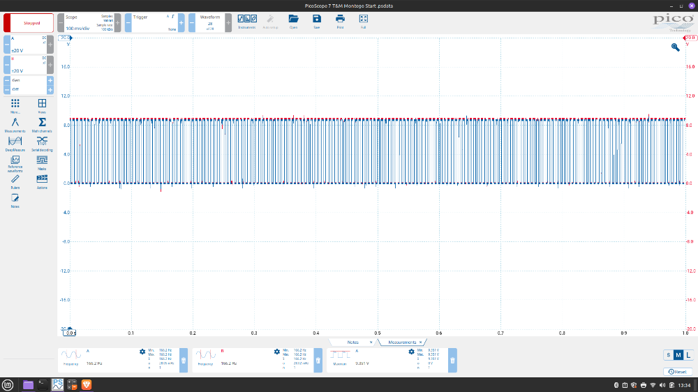
Upon actually test driving the car, I noted a significant misfire/poor running only when going up an incline, lugging the engine around 1500 RPM in a high gear. This was very similar to PHAD Ivan's video listed above. However, the alternator would not quite stop charging for me. In fact the alternator was communicating perfectly at all other times, except when this significant misfire would occur.
We can see that the voltage regulator on the GENMON (blue) trace, actually stops communicating/pulling the PCM voltage to ground during the misfire event. This was very consistent and repeatable.
I believe that at times when the miss became a bit worse (due to driving habits, fuel quality, or some other engine dynamic varible) the regulator would shut down all together and thus stop charging the vehicle.
Customer states she had no idea if or when spark plugs were changed so I pulled one from the front bank, and they were the worse plugs I personally have seen. Spec gap is 0.054" and these were worn nubbins that measured .090-.095". I replaced the spark plugs and test drove it for over 100 miles in varied loads and conditions and the alternator/regulator never missed a beat!
I returned the vehicle today. Will update if I ever hear of anymore issues related to this. Thanks!
Please Log in or Create an account to join the conversation.
- Noah
-

- Offline
- Moderator
-
- Posts: 5037
- Thank you received: 1119
Please Log in or Create an account to join the conversation.
- Tyler
-
- Offline
- Moderator
-
- Full time HACK since 2012
- Posts: 6126
- Thank you received: 1542
Please Log in or Create an account to join the conversation.