*** Restricting New Posts to SD Premium Members ONLY *** (09 May 2025)

Just made a new account? Can't post? Click above.

Help us help you. By posting the year, make, model and engine near the beginning of your help request, followed by the symptoms (no start, high idle, misfire etc.) Along with any prevalent Diagnostic Trouble Codes, aka DTCs, other forum members will be able to help you get to a solution more quickly and easily!

2003 Cadillac CTS with high voltage on the 5 v reference line2

  • Marti
  • Marti's Avatar Topic Author
  • Offline
  • Premium Member
  • Premium Member
More
3 years 7 months ago #54733 by Marti
After watching ScannerDanner Video, chapter 10 on circuit integrity, I applied the ECT test mentioned there. With KOEO, and all sensors plugged in, but I unplugged the ECT and shorted the connector from sensor(ye) to ground (tan wire) and checked the DTC to see if it went to "Circuit low". It did not. Then I shorted the sensor wire (ye) to the engine block and checked the DTCs and it now reads "circuit low" for the ECT. My focus now is on why the tan shared ground wire is not grounding this ECT circuit? I already showed this ground line goes to ECM connector 1, at pin 26, and to each of these: MAF, CMP(ground wire color is red/bk) and ECT. Any suggested next steps? Should I repeat the test while unplugging the MAF? Or unplug battery and see if there is continuity between that shared ground line (mostly tan wires) and any other line like the 12 v red at Pin 2 on MAF?...

Please Log in or Create an account to join the conversation.

  • VegasJAK
  • VegasJAK's Avatar
  • Offline
  • Platinum Member
  • Platinum Member
  • Silencing the Parts Cannon
More
3 years 7 months ago - 3 years 7 months ago #54734 by VegasJAK
Work on the tan ECT ground wire being open. That tan wire goes to splice S111. Find that splice. If you cannot find the splice work backwards from the ECT checking the tan wire ever couple of inches for continuity. Finding where that tan wire is open is critical to move forward.

Sorry to harp, but the MAF ground (tan) wire does not go to the shared ground of the ECT, IAT and CMP... it is independent and connects to the ECM at connector C1 pin 51. But worry about that after you find the open in the ECT ground.

Test light can be your best friend looking for opens. Attach to battery positive and probe along wire. You're doing good keep it up.

"an open mind let's knowledge flow in and wisdom flow out for a man who has neither never listens to those who have both".
Being wrong doesn't bother me, it's being right and not understanding why that does
Last edit: 3 years 7 months ago by VegasJAK.

Please Log in or Create an account to join the conversation.

  • Marti
  • Marti's Avatar Topic Author
  • Offline
  • Premium Member
  • Premium Member
More
3 years 7 months ago #54761 by Marti
Thanks for the encouragement. Can you send me an image of what S111 joint looks like?

Please Log in or Create an account to join the conversation.

  • VegasJAK
  • VegasJAK's Avatar
  • Offline
  • Platinum Member
  • Platinum Member
  • Silencing the Parts Cannon
More
3 years 7 months ago #54765 by VegasJAK
Sorry no. It's a wrapped loom of wires. You have to open the loom and locate the splice. Tan wires along with the red/black wire. As with the damaged wires you found behind the battery box look for contact points.

"an open mind let's knowledge flow in and wisdom flow out for a man who has neither never listens to those who have both".
Being wrong doesn't bother me, it's being right and not understanding why that does

Please Log in or Create an account to join the conversation.

  • Marti
  • Marti's Avatar Topic Author
  • Offline
  • Premium Member
  • Premium Member
More
3 years 7 months ago #54769 by Marti
since the ground lines voltage is about 8.5 v at each of the sensors: MAF, ECT, and CMP, and I had the bad wires that were shorting just below the MAF, I assume there is a short to power on the 12 v (line 2 on the MAF). So I found the supply line for this power feed, and disconnected it at the fuse box (under hood), I also disconnected the other end of this red line at the MAF --and then I bypassed the red MAF wire (line 2 on the MAF) with a 12 volt feed to the MAF. I still get high v on the ground lines all around (rats!). When I pull the 12 v supply line off the MAF, then the ground lines (mostly tan lines) drop from about 8.5 v to about 5 volts. The screenshot shows the fuse box and where the power feed originates (ECM fuse pink at 10 )

Please Log in or Create an account to join the conversation.

  • VegasJAK
  • VegasJAK's Avatar
  • Offline
  • Platinum Member
  • Platinum Member
  • Silencing the Parts Cannon
More
3 years 7 months ago - 3 years 7 months ago #54770 by VegasJAK
CMP also has a 12v feed... pink wire from fuse block that's pin 10... MAF is pin 16 of the fuse block. That's the under hood fuse block shown in the picture not the ECM.

"an open mind let's knowledge flow in and wisdom flow out for a man who has neither never listens to those who have both".
Being wrong doesn't bother me, it's being right and not understanding why that does
Last edit: 3 years 7 months ago by VegasJAK.

Please Log in or Create an account to join the conversation.

  • Marti
  • Marti's Avatar Topic Author
  • Offline
  • Premium Member
  • Premium Member
More
3 years 7 months ago #54786 by Marti
Yes, my bad on mixing up the fuse numbers. You are correct, the MAF pin 2 red line is power from pin 16, called Manifold -10 amp on my fuse box. I tried taking this Manifold fuse out and the three ground lines (ECT, CMP and MAF) still had high volts, about 8 v. So i used an ohm meter and determined which line from the fusebox connector went to the MAF. When I found this i bypassed that line by disconnecting it (depinned it) from the connector and ran a new power feed line to the MAF pin 2. I thought that would eliminate my short to power, but I still saw high volts on those ground lines.

Please Log in or Create an account to join the conversation.

  • Marti
  • Marti's Avatar Topic Author
  • Offline
  • Premium Member
  • Premium Member
More
3 years 7 months ago #54787 by Marti
Can we get Paul Danner to look at this?

Please Log in or Create an account to join the conversation.

  • Marti
  • Marti's Avatar Topic Author
  • Offline
  • Premium Member
  • Premium Member
More
3 years 7 months ago #54880 by Marti
From your March 4th, 10:00 posting you said I have an open in the tan ground line from the ECT. That line is shared with the CMP and MAF. Is that my focus to find that open? The ECT wiring is very difficult to access because it runs behind the engine near the firewall.

Would a ground test using a tail light bulb ( 500 milliamps at 12 volts) verify that the tan ground line from the ECT has continuity under load?

Please Log in or Create an account to join the conversation.

More
3 years 6 months ago #55572 by SGT MAC
Did you find the solution to this? My 2003 CTS is getting 12.5V on the CMP power wire, 11.5V on the signal wire, and 0V on the ground. From reading the previous posts, I should not have that on the signal wire, correct?

The car itself is perplexing me. It did not give any codes for the CMP sensor, just a misfire on the 2-4-6 cylinders. I discovered the wires bare at the CMP connector is the only reason I am going after this. I replaced the coil pack, checked the timing belt, fuel pressure, ohmed out the injectors, etc. The car will crank but not start, nor even hit with everything connected. Here is the crazy part-it will start and run on 3 cylinders, only if the 2-4-6 plugs are out. If you put all 3 plugs in, even without the coil, it will not start, or even try to, it just cranks. I removed the catalytic convertor from that side, no help.

Any advice on trouble shooting that voltage, or anything else is much appreciated.

Please Log in or Create an account to join the conversation.

  • VegasJAK
  • VegasJAK's Avatar
  • Offline
  • Platinum Member
  • Platinum Member
  • Silencing the Parts Cannon
More
3 years 6 months ago #55574 by VegasJAK
Marti's problem was a bad common ground on the CMP, MAF/IAT, ECT sensors resulting in a no start/run. You have a run but only on bank 1. The 12v,12v,0v is good. The ground should be around .100mv. To make sure of the ground using the DVOM, KOEO, black lead to the CMP ground red lead to battery positive. Should read 12v. Faster is test light attached to battery+ touch ground wire. Test light should light.
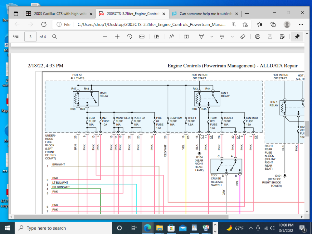
Crank sensor (CKP) controls spark. You have spark to coil 1 but not coil 2. Check the Blk/Wt ground wire at coil 2. It's common with coil 1 ground. You lost the ground most likely at the eyelet or somewhere in-between the eyelet and coil 2. Test light to battery+ can check that ground fast. KOEO touch test light to ground, Blk/Wt wire at both coils. IMO, coil 2 ground doesn't light.

"an open mind let's knowledge flow in and wisdom flow out for a man who has neither never listens to those who have both".
Being wrong doesn't bother me, it's being right and not understanding why that does

Please Log in or Create an account to join the conversation.

More
3 years 6 months ago - 3 years 6 months ago #55575 by SGT MAC
I will check that now. My question is: why would it only run with the bank 2 spark plugs physically removed? If you put them in, even without the coil on or plugged in, it will not start. Take the plugs out and it will start. It seems like it has nothing to do with having spark there or not, since it will start and run if the bank 2 side is vented through the plugs. I tried pulling the catalytic convertor in case it was clogged, but it made no difference.
Last edit: 3 years 6 months ago by SGT MAC.

Please Log in or Create an account to join the conversation.

  • VegasJAK
  • VegasJAK's Avatar
  • Offline
  • Platinum Member
  • Platinum Member
  • Silencing the Parts Cannon
More
3 years 6 months ago #55576 by VegasJAK
Can't answer that. Puzzling. :unsure: That model seems to have wiring chafing problems though.

"an open mind let's knowledge flow in and wisdom flow out for a man who has neither never listens to those who have both".
Being wrong doesn't bother me, it's being right and not understanding why that does

Please Log in or Create an account to join the conversation.

More
3 years 6 months ago #55577 by SGT MAC
I got 12V between positive and the black/white wire. Also 12V between CMP sensor ground and battery positive.

Please Log in or Create an account to join the conversation.

More
3 years 6 months ago #55578 by SGT MAC
Is there a way, that you know of, to test the CMP sensor with only a DMM? I cannot find a reading for it on the tech 2. All other reading seem to be OK. The IAT is reading 86 degrees F, Start up IAT says -54 degrees F. I don't know if that is a variable value, or a setting though.

Please Log in or Create an account to join the conversation.

  • VegasJAK
  • VegasJAK's Avatar
  • Offline
  • Platinum Member
  • Platinum Member
  • Silencing the Parts Cannon
More
3 years 6 months ago #55579 by VegasJAK
You tested the Blk/Wt ground wire at both coils and have good grounds for both, Yes.

If yes, check coil pack 2 for 12v on the pink power wire. Both coils have a pink 12v wire and go to the same ign mod fuse but have separate wires off the fuse.

"an open mind let's knowledge flow in and wisdom flow out for a man who has neither never listens to those who have both".
Being wrong doesn't bother me, it's being right and not understanding why that does

Please Log in or Create an account to join the conversation.

  • VegasJAK
  • VegasJAK's Avatar
  • Offline
  • Platinum Member
  • Platinum Member
  • Silencing the Parts Cannon
More
3 years 6 months ago #55580 by VegasJAK

Is there a way, that you know of, to test the CMP sensor with only a DMM?

Yes. With DMM connected to CMP sig wire KOEO you should see 12v, bump key or turn engine by hand voltage will drop to 0v. 12v to 0v as you move crank slowly. CKP sig the same.

"an open mind let's knowledge flow in and wisdom flow out for a man who has neither never listens to those who have both".
Being wrong doesn't bother me, it's being right and not understanding why that does
The following user(s) said Thank You: Noah

Please Log in or Create an account to join the conversation.

More
3 years 6 months ago #55583 by SGT MAC
I tested both grounds, both power wires to the coils. They all look good. The CMP sensor passed the test as well. Triple checked the timing belt as well. This one has me stumped.
Anything else you can think of?

Please Log in or Create an account to join the conversation.

  • VegasJAK
  • VegasJAK's Avatar
  • Offline
  • Platinum Member
  • Platinum Member
  • Silencing the Parts Cannon
More
3 years 6 months ago #55592 by VegasJAK
Unplug the CMP. On the harness side, KOEO, what voltages do you get on each of the three wires.

"an open mind let's knowledge flow in and wisdom flow out for a man who has neither never listens to those who have both".
Being wrong doesn't bother me, it's being right and not understanding why that does

Please Log in or Create an account to join the conversation.

More
3 years 6 months ago #55594 by SGT MAC
The same voltages. About 12.5V for power, 11.5V for signal, less than .1 for ground.

Please Log in or Create an account to join the conversation.

Time to create page: 0.399 seconds