*** Restricting New Posts to SD Premium Members ONLY *** (09 May 2025)

Just made a new account? Can't post? Click above.

Help us help you. By posting the year, make, model and engine near the beginning of your help request, followed by the symptoms (no start, high idle, misfire etc.) Along with any prevalent Diagnostic Trouble Codes, aka DTCs, other forum members will be able to help you get to a solution more quickly and easily!

2003 Cadillac CTS with high voltage on the 5 v reference line2

  • Marti
  • Marti's Avatar Topic Author
  • Offline
  • Premium Member
  • Premium Member
More
3 years 7 months ago #54636 by Marti
CTS cranks but no start and the several codes showing high voltage on sensors (MAF, Camshaft position sensor (CMP), APP, ECT ). I did find the 5 lines going to the MAF were rubbing on the frame and shorting so I fixed them. I replaced the MAF, CMP and ECT sensors and replaced the MAF connector. I got some help for JustAnswers.com here www.google.com/url?sa=t&rct=j&q=&esrc=s&...qp9ckOu9QLdo6IEFR4hv

I also attached the scanner readout:

This browser does not support PDFs. Please download the PDF to view it: Download PDF


Can someone guide me on checking the computer grounds? The wiring diagram on JustAnswers.com is unclear on which lines are for the ECM ground. I verified that the ECM external ground is good by running current and showing a good ground.

This browser does not support PDFs. Please download the PDF to view it: Download PDF

This browser does not support PDFs. Please download the PDF to view it: Download PDF

This browser does not support PDFs. Please download the PDF to view it: Download PDF

This browser does not support PDFs. Please download the PDF to view it: Download PDF

Please Log in or Create an account to join the conversation.

  • VegasJAK
  • VegasJAK's Avatar
  • Offline
  • Platinum Member
  • Platinum Member
  • Silencing the Parts Cannon
More
3 years 7 months ago - 3 years 7 months ago #54640 by VegasJAK
I see two things I think are causing your problems. First I think 12v from your cmp wiring is shorted to the cmp ground. Second you have the two tan ground wires at the MAF (3&4) reversed.

What's happening is 12v from your cmp is feeding through the cmp shared ground with the ect and ait to the MAF ground which you have reversed. The MAF ground is not shared.

Cleanup the MAF wiring first. Your cmp should be 12v power 12v sig and <100mv ground.

"an open mind let's knowledge flow in and wisdom flow out for a man who has neither never listens to those who have both".
Being wrong doesn't bother me, it's being right and not understanding why that does
Last edit: 3 years 7 months ago by VegasJAK.

Please Log in or Create an account to join the conversation.

  • Marti
  • Marti's Avatar Topic Author
  • Offline
  • Premium Member
  • Premium Member
More
3 years 7 months ago #54664 by Marti
I switched the 3and 4 lines to the MAF and could not find any short to power on the CMP sensor. Even depinned the connector there but it looks good as there is no shorting in the connector (see photo). I had traced the MAF tan lines to their pins on the ECU, and now the shared ground is on MAF pin 4 instead of the middle pin. Should I switch them back?

Please Log in or Create an account to join the conversation.

  • Marti
  • Marti's Avatar Topic Author
  • Offline
  • Premium Member
  • Premium Member
More
3 years 7 months ago #54665 by Marti
I also disconnected battery and found continuity on CMP sensor line at pin 3, also found no continuity from the ECM fuse 15 amp, to the CMP sensor pin 1. The colors are different than wiring diagram on CMP. They are as follows from pins 1 to 3, Red/bk , Brn/wh , tan. The red/bk is continuous with the ECT pin 2and MAF pin 3 (now pin 4 after switching yesterday)

Please Log in or Create an account to join the conversation.

  • VegasJAK
  • VegasJAK's Avatar
  • Offline
  • Platinum Member
  • Platinum Member
  • Silencing the Parts Cannon
More
3 years 7 months ago - 3 years 7 months ago #54666 by VegasJAK

also found no continuity from the ECM fuse 15 amp, to the CMP sensor pin 1.
Fuse 15 is 12v. CMP pin 1 is a ground. You won't find continuity there.

The colors are different than wiring diagram on CMP. They are as follows from pins 1 to 3, Red/bk , Brn/wh , tan. The red/bk is continuous with the ECT pin 2and MAF pin 3 (now pin 4 after switching yesterday)
The Red/Blk is 12v it should not be continuous with ECT pin 2 and MAF pin 4. Those are Tan ground wires. The MAF Tan ground should be pin 4 to ECM pin 51 and not shared with any other ground. The Tan ground wire pin 3 at the MAF connector is the IAT ground. It is the shared ground with the ECT pin 2 Tan wire and CMP pin 1 Tan ground wire.

"an open mind let's knowledge flow in and wisdom flow out for a man who has neither never listens to those who have both".
Being wrong doesn't bother me, it's being right and not understanding why that does
Last edit: 3 years 7 months ago by VegasJAK.

Please Log in or Create an account to join the conversation.

  • Marti
  • Marti's Avatar Topic Author
  • Offline
  • Premium Member
  • Premium Member
More
3 years 7 months ago #54670 by Marti
Ok so I’ll switch the MAF tan lines back so they lead to the ECU pins like pin 51 for tan line at MAF pin 4. Should I depin the CMP so the tan line is on pin 1. ?

Please Log in or Create an account to join the conversation.

  • VegasJAK
  • VegasJAK's Avatar
  • Offline
  • Platinum Member
  • Platinum Member
  • Silencing the Parts Cannon
More
3 years 7 months ago - 3 years 7 months ago #54675 by VegasJAK
Yes. CMP pin 1 Tan is the ground, pin 2 Brn/wht is signal and pin 1 Rd/blk is 12v.

Just to clarify, MAF pin 4 tan wire goes to ECM pin 51, pin 3 tan wire is the IAT ground wire that goes to S111 splice and pin 1 Tan is the IAT signal wire that goes to ECM pin 57. Pin 5 yellow is the MAF signal wire. It goes to pin 56 of ECM. Pin2 Rd/blk is 12v feed from fuse box.

"an open mind let's knowledge flow in and wisdom flow out for a man who has neither never listens to those who have both".
Being wrong doesn't bother me, it's being right and not understanding why that does
Last edit: 3 years 7 months ago by VegasJAK.

Please Log in or Create an account to join the conversation.

  • Marti
  • Marti's Avatar Topic Author
  • Offline
  • Premium Member
  • Premium Member
More
3 years 7 months ago #54680 by Marti
I swapped the MAF tan lines at 3 and 4 back to where they were originally. I check them for continuity at the corresponding ECU pins and they are correct. As requested, I swapped the end CMP sensor pins: red/bk over to pin 3 and the tan or pinkish line was moved to pin 1. The volts for CMP pins 1-3 are unchanged from what they were, with 12 v, 12 v and 8 volts respectively. Also, the red/bk line now on pin 3 has continuity with the ground wires on the MAF pin 3 (middle pin) and ECT ground pin. The red/bk line is 0.010 v when the MAF is unplugged. But plug in the MAF and the shared ground lines on the 3 sensors all go to 8v. On the MAF plugged in the grounds and both sensor lines are high, about 9 v. The MAF and connector are both new.

Please Log in or Create an account to join the conversation.

  • VegasJAK
  • VegasJAK's Avatar
  • Offline
  • Platinum Member
  • Platinum Member
  • Silencing the Parts Cannon
More
3 years 7 months ago #54689 by VegasJAK
Let's just do the CMP first.

Pin 1= Tan (ground)
Pin 2= Brn/Wht (signal)
Pin 3= Pink (12v)

Note I show pink on pin 3. This per the wiring diagram. You previously said the 12v was Red/Blk so I changed pink to red/blk.

You now mention a tan pinkish wire associated with the CMP. Confirm please that the three CMP wires are pink, tan and Brn/Wht.

"an open mind let's knowledge flow in and wisdom flow out for a man who has neither never listens to those who have both".
Being wrong doesn't bother me, it's being right and not understanding why that does

Please Log in or Create an account to join the conversation.

  • Marti
  • Marti's Avatar Topic Author
  • Offline
  • Premium Member
  • Premium Member
More
3 years 7 months ago #54693 by Marti
Tha cam position sensor wire colors on the wiring diagram are different than those in my car and I pulled back the tape on the harness they go all the way and are not spliced. See pic. I don’t think we can use the colors but trace which is the ground by continuity to the right pin on the ECM

Please Log in or Create an account to join the conversation.

  • Marti
  • Marti's Avatar Topic Author
  • Offline
  • Premium Member
  • Premium Member
More
3 years 7 months ago #54696 by Marti
I’m using Alldata wiring diagrams which do not show a red/bk line To the CMP sensor. Do you have access to Mitchell1 diagrams? They may be more accurate.

Please Log in or Create an account to join the conversation.

  • VegasJAK
  • VegasJAK's Avatar
  • Offline
  • Platinum Member
  • Platinum Member
  • Silencing the Parts Cannon
More
3 years 7 months ago #54704 by VegasJAK
Marti,
Wiring colors are always a problem they differ from car to car and model to model. Too make it worse it's different on alldata to Mitchell ECT...

Knowing some basics and testing and tracing wires works better in a lot of cases.

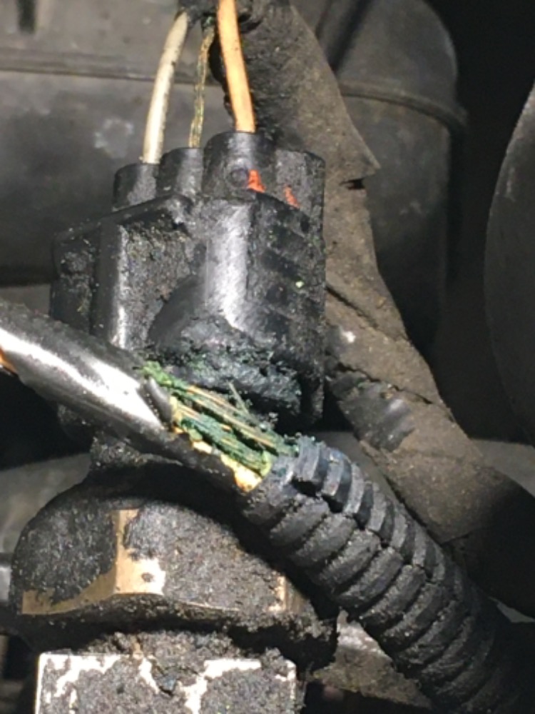
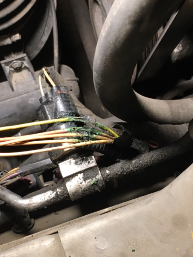
I'm retired and on a fixed income so I don't have any subscriptions anymore. I can guide you but it will take a little more work and patience. Your problem is crossed wiring and a short to power. You have some wiring problems due to pinched and worn wiring looms which makes thing more difficult and aggravating. Here to help you.

"an open mind let's knowledge flow in and wisdom flow out for a man who has neither never listens to those who have both".
Being wrong doesn't bother me, it's being right and not understanding why that does

Please Log in or Create an account to join the conversation.

  • VegasJAK
  • VegasJAK's Avatar
  • Offline
  • Platinum Member
  • Platinum Member
  • Silencing the Parts Cannon
More
3 years 7 months ago #54705 by VegasJAK
For sure, the center Brn/wht is your signal wire. The wire on the left in photo looks white but further back it's pink. I have found ground wires red with a black tracer before. Trace the pink back it should go to a fuse source.

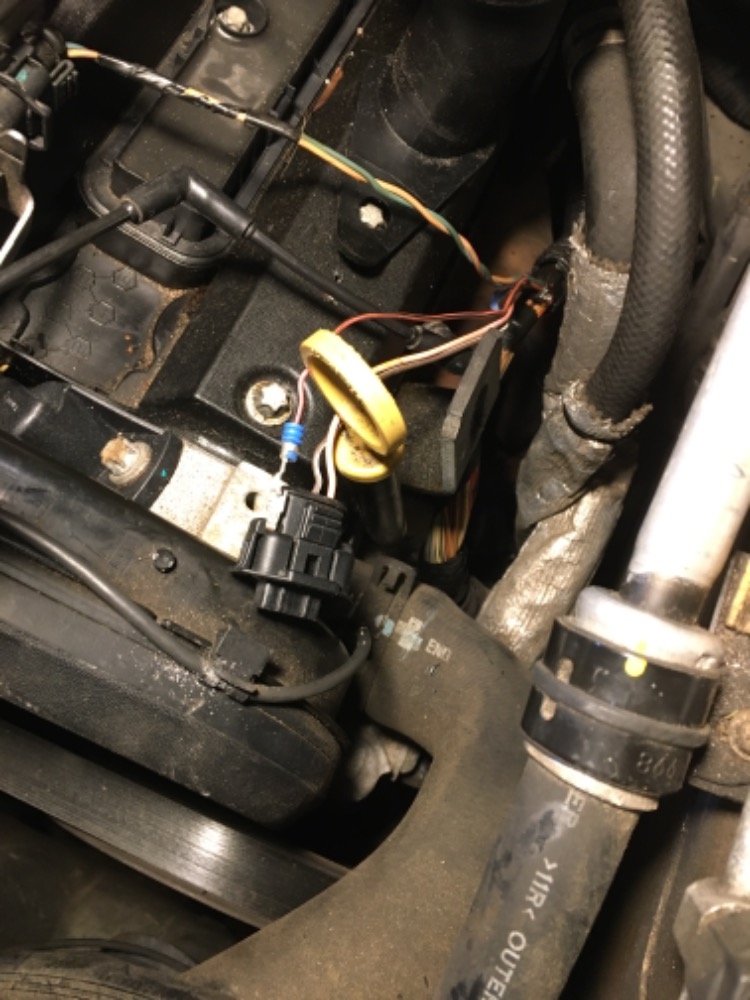
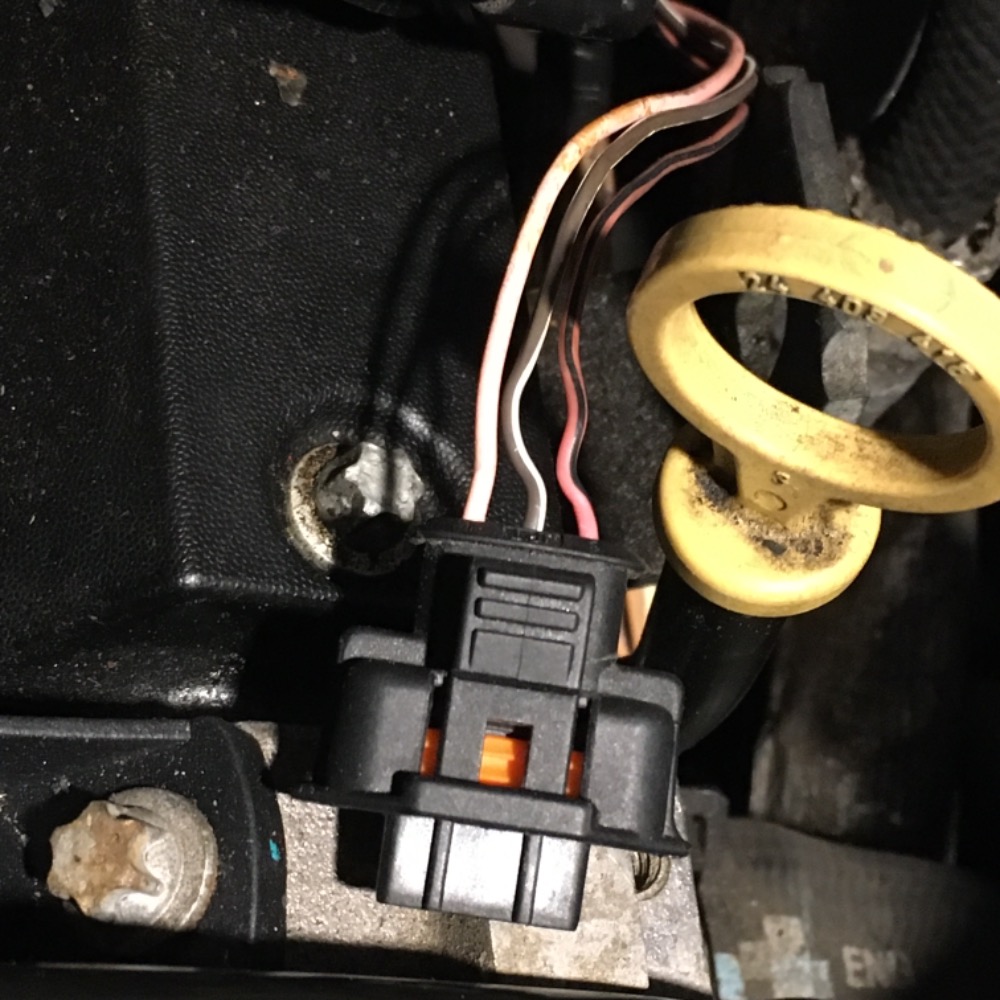
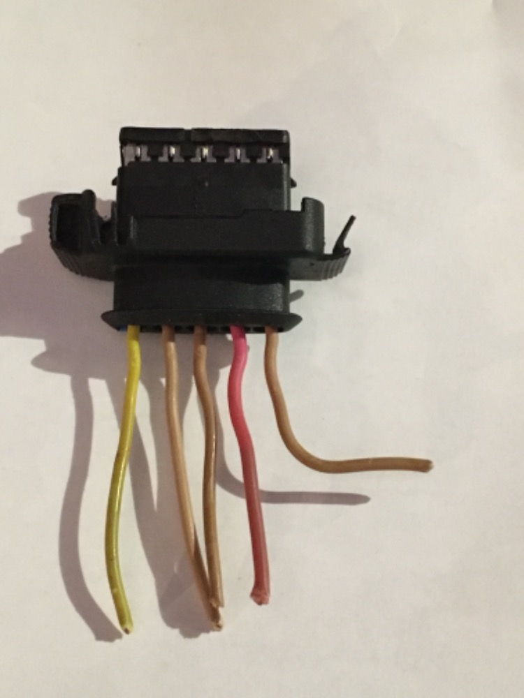
Let's see a photo of the wires on the MAF and ECT.

"an open mind let's knowledge flow in and wisdom flow out for a man who has neither never listens to those who have both".
Being wrong doesn't bother me, it's being right and not understanding why that does

Please Log in or Create an account to join the conversation.

  • Marti
  • Marti's Avatar Topic Author
  • Offline
  • Premium Member
  • Premium Member
More
3 years 7 months ago #54708 by Marti
Ok thanks and I will check PIN numbers on the ECU and sensors to confirm which is which. Is it possible my prob of high volts on ground lines is caused by an open ground in that shared ground or MAF pin 4? Also, are you able to see my troubleshooting dialogues in Justanswere? I’ll copy the pic of exposed wires shorting together upstream of the MAF sensor

Please Log in or Create an account to join the conversation.

  • VegasJAK
  • VegasJAK's Avatar
  • Offline
  • Platinum Member
  • Platinum Member
  • Silencing the Parts Cannon
More
3 years 7 months ago - 3 years 7 months ago #54712 by VegasJAK

Is it possible my prob of high volts on ground lines is caused by an open ground in that shared ground or MAF pin 4

Yes. Possible.

I have viewed your posts on the linked forum. I believe you have more wiring problems due to bad wiring but they can be found with the correct testing methods. Be mindful of using ohm testing it's not reliable. When looking for shorts to ground using an ohm meter you have to isolate the wire first.

Post photos of the MAF and ECT wiring at connectors. I would like to see it to give me a reference to work from. Thanks

I did find a photo of the MAF that you cut off. Are the wiring positions original?

Which CMP photo is the original wiring positions?

"an open mind let's knowledge flow in and wisdom flow out for a man who has neither never listens to those who have both".
Being wrong doesn't bother me, it's being right and not understanding why that does
Last edit: 3 years 7 months ago by VegasJAK.

Please Log in or Create an account to join the conversation.

  • Marti
  • Marti's Avatar Topic Author
  • Offline
  • Premium Member
  • Premium Member
More
3 years 7 months ago #54713 by Marti
The CMP original wiring has red/bk on pin 1 where the diagram has a tan shared sensor ground. The other wires are similar to the diagram colored lines as seen in my picture. I now have it connected as originally seen before my radiator replacement when the car ran. I’ll use a brake light bulb to power each ground line and the 12 volt B+ lines after work. Also, because I hit the ABS module connector putting the radiator in I’ll visually inspect it. I also removed and ohm tested the ACellerator pedal position module so must I calibrate this before it will start?

Please Log in or Create an account to join the conversation.

  • Marti
  • Marti's Avatar Topic Author
  • Offline
  • Premium Member
  • Premium Member
More
3 years 7 months ago #54714 by Marti
On the MAF connector shown, the ye line on pin 5 is towards the engine, or downstream in the intake hose.

Please Log in or Create an account to join the conversation.

  • VegasJAK
  • VegasJAK's Avatar
  • Offline
  • Platinum Member
  • Platinum Member
  • Silencing the Parts Cannon
More
3 years 7 months ago - 3 years 7 months ago #54716 by VegasJAK
Connect the MAF wiring back to it's original positions. We know now that the wiring diagram is not color or position matched to your caddie. Take care reattaching those tan wires. To bad they did not have a tracer color to identify each circuit.

Get yourself a test light. They are cheap and your best friend working with circuits.

Once everything is back to original we can test and find opens or shorts in the system and get you back running.

"an open mind let's knowledge flow in and wisdom flow out for a man who has neither never listens to those who have both".
Being wrong doesn't bother me, it's being right and not understanding why that does
Last edit: 3 years 7 months ago by VegasJAK.

Please Log in or Create an account to join the conversation.

  • VegasJAK
  • VegasJAK's Avatar
  • Offline
  • Platinum Member
  • Platinum Member
  • Silencing the Parts Cannon
More
3 years 7 months ago #54721 by VegasJAK
When reconnecting the wires to the MAF pigtail, the yellow and pink wires on the connector pigtail go to their respective yellow and pink wires from the harness. As the pigtail wires are in their original positions this is where they belong, its the three tan wires which have to be identified. I would unplug the C1 connector at the ECM. Using a nine volt battery, connect the black lead of your volt meter to the neg post of the 9 volt battery. Back probe the tan wire at the disconnected C1 connector, should be the 7th wire position back from the end of the C1 connector between a gray wire and a yellow wire. With a jumper wire, connect one end to the positive post of the 9 volt battery, the other end to the tan wire you back probed. Set your volt meter to dc volts. Using the red lead, touch each of the three tan wires you're trying to reconnect one at a time and note the one that has 9 volts on it. That will be the AIT signal wire that attaches to the outside tan wire on the MAF connector. Do the same process to identify the MAF ground. Jumper wire from battery positive to the tan wire in the C1 connector 13 wire positions back from the end of the connector between a light blue/black and light blue wire. Touch the red lead to the remaining two tan wires and note which one has 9 volts. That will be the MAF single ground which attaches to tan wire next to the yellow wire on the MAF connector. The remaining tan wire on the harness connects to the remaining tan wire on the MAF pigtail. From left to right on the pigtail you should have yellow, tan, tan, pink, tan.

If I over simplified this, sorry, just wanted to be clear. Do the above with the key off. If you're nervous about the 9v test, you can disconnect the car battery. Using the Ohm meter can give you a false reading so do not use it. Use the volt meter instead.

"an open mind let's knowledge flow in and wisdom flow out for a man who has neither never listens to those who have both".
Being wrong doesn't bother me, it's being right and not understanding why that does

Please Log in or Create an account to join the conversation.

  • Marti
  • Marti's Avatar Topic Author
  • Offline
  • Premium Member
  • Premium Member
More
3 years 7 months ago #54729 by Marti
The current symptoms are: high voltage (8 volts) on ground lines in MAF, ECT and CMP when all are plugged in, they drop when the MAF is unplugged. Trying to start the car, there is no RPM on the dash, and on my Autel scanner it shows no counts on the CMP sensor. The radio has a message "engine hot-, turn off AC". The main relay in the fuse box (engine compartment) seems very warm when KOEO. What is my focus for the diagnostic at this point?

This browser does not support PDFs. Please download the PDF to view it: Download PDF

This browser does not support PDFs. Please download the PDF to view it: Download PDF

Please Log in or Create an account to join the conversation.

Time to create page: 0.323 seconds