2003 Cadillac CTS with high voltage on the 5 v reference line
- Marti
-
 Topic Author
- Offline
- Premium Member
-

- Posts: 136
- Thank you received: 8
Please Log in or Create an account to join the conversation.
- jreardon
-
- Offline
- Platinum Member
-

- Posts: 521
- Thank you received: 198
Please Log in or Create an account to join the conversation.
- Marti
-
Topic Author
- Offline
- Premium Member
-
- Posts: 136
- Thank you received: 8
Please Log in or Create an account to join the conversation.
- Marti
-
Topic Author
- Offline
- Premium Member
-
- Posts: 136
- Thank you received: 8
Please Log in or Create an account to join the conversation.
- jreardon
-
- Offline
- Platinum Member
-
- Posts: 521
- Thank you received: 198
if the signal wire's still low check for a short to ground or possibly an open in the signal wire. Don't forget to check and make sure ignition 1 voltage is present at pin 2 and you have 5v ref at pin 4. We don't care about IAT and we already fixed the ground.

www.docdroid.net/glLsFj1/p0102-pdf
Please Log in or Create an account to join the conversation.
- Marti
-
Topic Author
- Offline
- Premium Member
-
- Posts: 136
- Thank you received: 8
Please Log in or Create an account to join the conversation.
- Marti
-
Topic Author
- Offline
- Premium Member
-
- Posts: 136
- Thank you received: 8
Please Log in or Create an account to join the conversation.
- Marti
-
Topic Author
- Offline
- Premium Member
-
- Posts: 136
- Thank you received: 8
Please Log in or Create an account to join the conversation.
- Marti
-
Topic Author
- Offline
- Premium Member
-
- Posts: 136
- Thank you received: 8
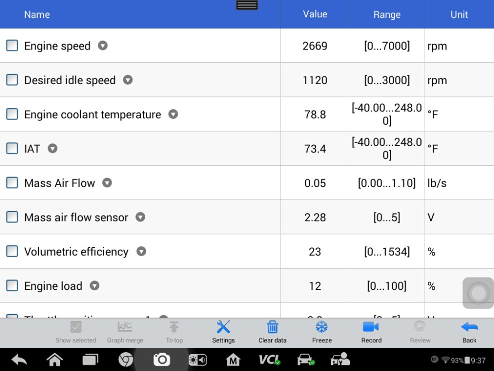
I unplugged the MAF sensor and the volts went to zero on the PID, It is about 1 v plugged in.
Please Log in or Create an account to join the conversation.
- Marti
-
Topic Author
- Offline
- Premium Member
-
- Posts: 136
- Thank you received: 8

Please Log in or Create an account to join the conversation.
- jreardon
-
- Offline
- Platinum Member
-
- Posts: 521
- Thank you received: 198
i don't measure any volts on the yellow line (sensor line).
I unplugged the MAF sensor and the volts went to zero on the PID
Any voltage on sensor wire after you unplug the MAF?
Maybe meter's not making contact or you're in the wrong wire. Pierce the wire and short signal to ground does PID read 0? Try to pull it up near 5 volts by shorting signal to 5V ref.
Check in OBD generic (maybe substitute value?)
Can you graph the PID and shake the harness about?
Please Log in or Create an account to join the conversation.
- Marti
-
Topic Author
- Offline
- Premium Member
-
- Posts: 136
- Thank you received: 8
Any voltage on sensor wire after you unplug the MAF? { 11 mv unplugged on yellow line MAF sensor line with KOEO, I get 1 v with it plugged in } { with the engine on, the MAF sensor line volts vary from 1.5 to 1.7 volts }
Maybe meter's not making contact or you're in the wrong wire. Pierce the wire and short signal to ground does PID read 0? { PID for MAF reads 8 mv }
Try to pull it up near 5 volts by shorting signal to 5V ref. { when I do this I get 5 V on the PID and by multimeter }
Check in OBD generic (maybe substitute value?) { I was able to use the EOBD in ISO 1430 but could not graph the MAF volts }
Can you graph the PID and shake the harness about? { shaking it varies the volts on the MAF sensor line very little, a few mv }
Please Log in or Create an account to join the conversation.
- VegasJAK
-

- Offline
- Platinum Member
-
- Silencing the Parts Cannon
- Posts: 566
- Thank you received: 140
Don't fire the parts cannon just yet. Let's see if someone else has an idea.
"an open mind let's knowledge flow in and wisdom flow out for a man who has neither never listens to those who have both".
Please Log in or Create an account to join the conversation.
- Marti
-
Topic Author
- Offline
- Premium Member
-
- Posts: 136
- Thank you received: 8
Please Log in or Create an account to join the conversation.
- VegasJAK
-
- Offline
- Platinum Member
-
- Silencing the Parts Cannon
- Posts: 566
- Thank you received: 140
"an open mind let's knowledge flow in and wisdom flow out for a man who has neither never listens to those who have both".
Please Log in or Create an account to join the conversation.
- Marti
-
Topic Author
- Offline
- Premium Member
-
- Posts: 136
- Thank you received: 8
Please Log in or Create an account to join the conversation.