2009 Chrysler Town & Country Touring 4.0L P2100 Throttle Actuator
- StupidRalph
-
 Topic Author
- Offline
- Junior Member
-

- Posts: 23
- Thank you received: 0
First off, I'm not a mechanic nor even a DIYer. Just a frustrated car owner who can't find a diagnostician. I apologize for any improper terminology.
Van in constant limp home mode. Started appearing intermittently. At first, I was able to turn vehicle off / on and it would come out of limp mode. Red lightning bolt flashes incessantly. Key dance pulls code P2100. My cheapo code reader doesn't even pull this code.
Throttle body looks new. But since it showed on my mechanics scan tool he recommended a new one. Replaced with new Mopar TB. Error code still persists. Unable to do a TB relearn as his tool wouldn't communicate. He now recommends a new pigtail and possibly pedal. I'm not opposed but I just don't want to pay just swap out working parts w/o proper diagnosis. I do suspect wiring issue. I'd just like to pinpoint which wire and where the open in the circuit occurs. I have already purchased 5183469AB Mopar 6 Way Wiring on Amazon. (Are the wire colors supposed to match my vehicle -- all 6 wires are purple). I'm a bit hesitant in cutting wires willy-nilly I do not think there is a short to ground since I tested for a short using multimeter and test light on negative battery post that did not illuminate. It appears previous owner may have had issue as PCM has possibly been replaced -- June 2016 sticker. Battery is new (12.38v) but has been sitting for a few months.
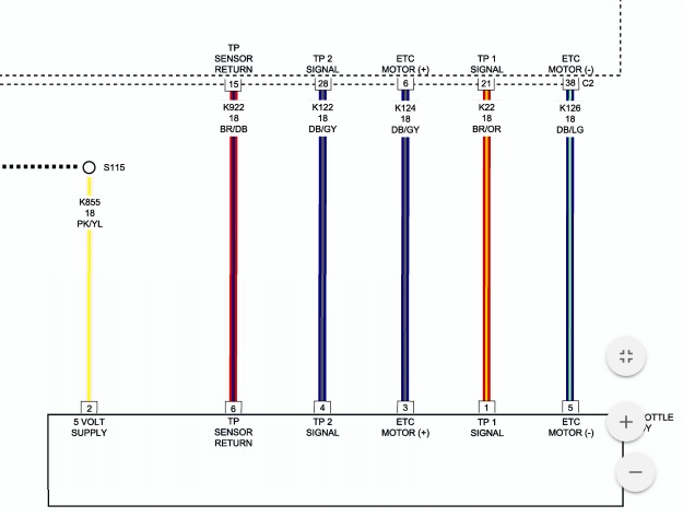
Below are the actual readings from my multimeter. There is no change in TP Sig 1 as the pedal is depressed.
Pin out
Pin 1 TP Sig 1 - 3.60 volts
Pin 2 5V Ref - 5.00 volts
Pin 3 ETC MTR (+) - No reading
Pin 4 TP Sig 2 - No reading
Pin 5 ETC MTR (-) - No reading
Pin 6 TP Sens Ground - Has continuity grounded to negative battery terminal.
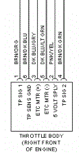
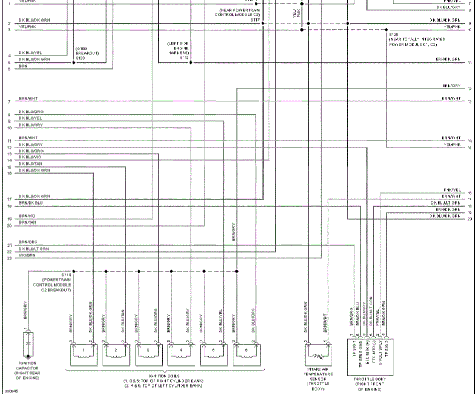
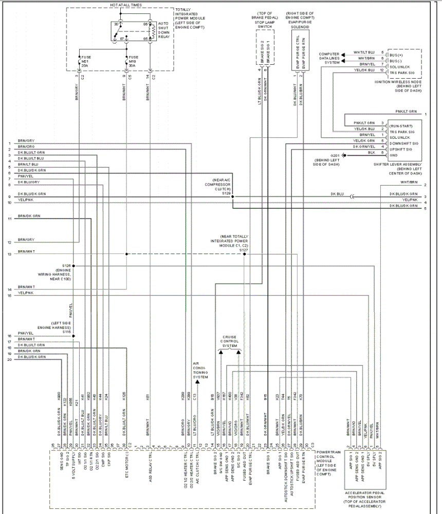
Complete wiring diagram can be found below. I took this snippet from page 66.
cardiagn.com/2009-system-wiring-diagrams-dodge-grand-caravan/
What are the next steps? I'm assuming piercing the wires without any reading at different intervals to see if I get a reading. Currently, I don't have anything to pierce the wire with and my local Lowe's nor Home Depot sold piercing probes. I'm located in Columbia, SC, USA.
Please Log in or Create an account to join the conversation.
- cheryl hartkorn
-
- Offline
- Platinum Member
-

- Posts: 694
- Thank you received: 130
Please Log in or Create an account to join the conversation.
- cheryl hartkorn
-
- Offline
- Platinum Member
-
- Posts: 694
- Thank you received: 130
Please Log in or Create an account to join the conversation.
- Tyler
-

- Offline
- Moderator
-

- Full time HACK since 2012
- Posts: 6115
- Thank you received: 1539
I do not think there is a short to ground since I tested for a short using multimeter and test light on negative battery post that did not illuminate
What you've actually done here is check for a short to power, instead of ground. No worries, that's a worthwhile check! Now I'd suggest doing the same thing, but with the test light connected to B+. Or, with the ohm meter, pins three and five should have no resistance to ground, power or each other.
While you're doing that, have a good look at the female pins inside the throttle connector itself. If any (especially pins three or five) look like they're spread open or otherwise have an abnormally large gap compared to the others, then that's a problem. If you find a pin fitment problem, replacing the connector is an option, but you may also have luck disassembling the connector and retensioning the pin.
Please Log in or Create an account to join the conversation.
- StupidRalph
-
Topic Author
- Offline
- Junior Member
-
- Posts: 23
- Thank you received: 0
Also, I'm guessing following cable back to PCM. And figuring which cable connects to TB and do some sort of integrity test on it.
@Cheryl
I only have the tools I bought recently to fix this issue.
2 Multimeters
Smart Probe
LED Test Light
Foxtech Scan Tool
Harbor Freight Centech Cable Tracer
Please Log in or Create an account to join the conversation.
- StupidRalph
-
Topic Author
- Offline
- Junior Member
-
- Posts: 23
- Thank you received: 0
No discrepancy among spacing on within the female connectors.
I'm still working on the additional suggestions. I can't quite follow the wiring.
Please Log in or Create an account to join the conversation.
- StupidRalph
-
Topic Author
- Offline
- Junior Member
-
- Posts: 23
- Thank you received: 0
I am viewing page 66 and 68 listed here.
cardiagn.com/2009-system-wiring-diagrams-dodge-grand-caravan/
Page 66
Page 68
Please Log in or Create an account to join the conversation.
- Tyler
-
- Offline
- Moderator
-
- Full time HACK since 2012
- Posts: 6115
- Thank you received: 1539
So pin 5 lights the test light when connected to B+... Is the PCM easily accessible? I'd suggest getting the test light connected up and lit, then disconnect the PCM. If the light goes out, you know that ground is inside the PCM. If the light remains lit, you know that wire is shorted to ground somewhere.
Please Log in or Create an account to join the conversation.
- StupidRalph
-
Topic Author
- Offline
- Junior Member
-
- Posts: 23
- Thank you received: 0
Unable to find on BBB Industries BUT I have identified the different pins on the connector that route to the TB connector. I also found a google image of the same connector pattern and marked the locations. See attached.
Please Log in or Create an account to join the conversation.
- StupidRalph
-
Topic Author
- Offline
- Junior Member
-
- Posts: 23
- Thank you received: 0
Please Log in or Create an account to join the conversation.
- StupidRalph
-
Topic Author
- Offline
- Junior Member
-
- Posts: 23
- Thank you received: 0
Pic 1 is most relevant. Pic2 - 4 just show where the wire routes through the vehicle.
Pic 1 shows C2 connector hanging down but also where the cable splices out to a gray connector. When the gray connector is unplugged the short disappears at the TB AND at the C2 connector. It also disappears on the bottom half of the connector. It does appear however on the pink/yellow (5v ref) on the top part of the connector.
Pic 2 shows the above view from the hood of the gray connector and main wiring harness. I've marked them with yellow *s.
Pic 3 shows more top part of connector, and more directional wire routing.
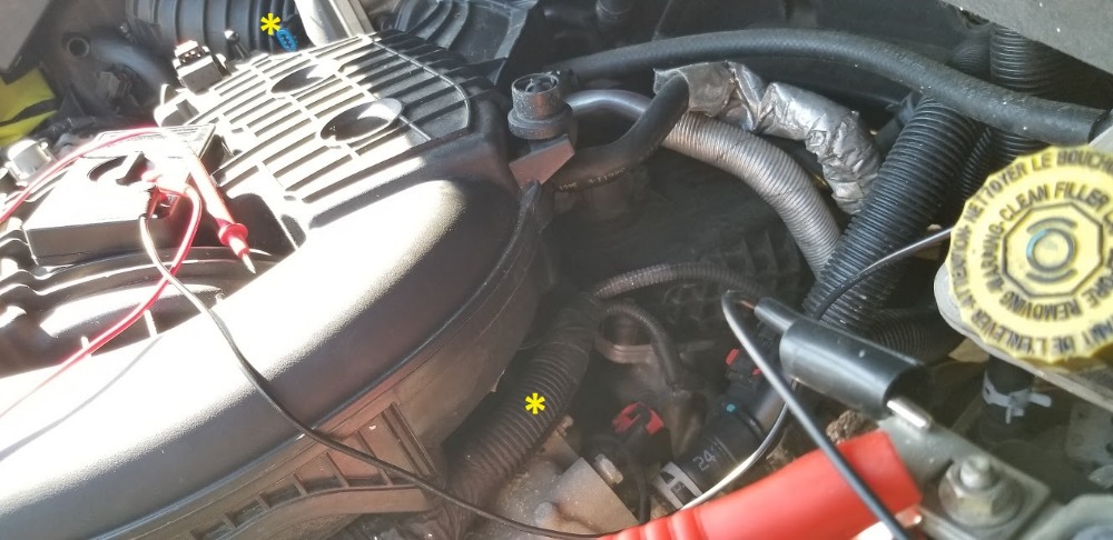
Pic 4 shows routing behind upper intake (?) plenum(?). (told you I wasn't a mechanic
 ) and also the TB connector in the background marked with yellow *.
 Please Log in or Create an account to join the conversation.
- StupidRalph
-
Topic Author
- Offline
- Junior Member
-
- Posts: 23
- Thank you received: 0
Can my wire tracer (fox and hound) help me?
I don't understand, if its short to ground, shouldn't that pull down the 5v ref. voltage considerably? Its 4.97 at the TB. But there is a 2nd 5v ref on the map sensor also at 4.97.
These two refs may be tied together i can't tell on wiring diagram.
Please Log in or Create an account to join the conversation.
- Ben
-
- Offline
- Platinum Member
-
- Posts: 1098
- Thank you received: 215
Sent from my SM-N920P using Tapatalk
Please Log in or Create an account to join the conversation.
- Tyler
-
- Offline
- Moderator
-
- Full time HACK since 2012
- Posts: 6115
- Thank you received: 1539
Please Log in or Create an account to join the conversation.
- cheryl hartkorn
-
- Offline
- Platinum Member
-
- Posts: 694
- Thank you received: 130
Please Log in or Create an account to join the conversation.
- Tyler
-
- Offline
- Moderator
-
- Full time HACK since 2012
- Posts: 6115
- Thank you received: 1539
StupidRalph, what is pin 5 at the TB doing with the PCM disconnected? That's the ETC- circuit, so (hopefully) the short to ground went away when you disconnected the PCM.
Like Cheryl suggested early on, now is the time to load test the ETC+ and - circuits. There's different ways you can do this, but the basic idea is to use the suspect wire in series with an electrical load. The easiest way would be to connect your test light to B+ and probe pin #3 or #5 at the TB (TB disconnected), then ground the corresponding pin at the PCM connector (PCM disconnected). Take care not to spread female pins, of course. The bulb should light brightly. If it doesn't, there's either a problem with your connections, or there's a problem with the wire.
")
Let us know if you need clarification.

Please Log in or Create an account to join the conversation.
- StupidRalph
-
Topic Author
- Offline
- Junior Member
-
- Posts: 23
- Thank you received: 0
The reason i say its shorted to ground is with C2 disconnected from PCM and connector on TB disconnected. My test light, lights green on pin 2 (5V ref) at TB and pin 29(5V ref) on C2 connector. No other pin lights test light nor shows voltage. However, when I unplug that gray connector, my test light does not illuminate on pin 2 at TB nor pin 29 on C2 connector. Nor the bottom part of the gray connector. The top part of the gray connector on 5v ref #1 pin illuminates the light green. It also illuminates on other pins at the gray connector but I havent identified those wires yet. I do know 5V ref #2 is in that gray connector as well.
I can upload a video if necessary.
Please Log in or Create an account to join the conversation.
- StupidRalph
-
Topic Author
- Offline
- Junior Member
-
- Posts: 23
- Thank you received: 0
So what is pin 5 on the actual TB doing and not the connector?
I do have an extra pigtail i can plug in to the TB to perform test.
Also, have the TB that came off of the van which also appears to be new.
Please Log in or Create an account to join the conversation.
- StupidRalph
-
Topic Author
- Offline
- Junior Member
-
- Posts: 23
- Thank you received: 0
Pin 5 nor pin 3 illuminate with test light connected to B+ with PCM C2 disconnected.
Pin 2 5V ref in this scenario illuminates green.
Please Log in or Create an account to join the conversation.
- Ben
-
- Offline
- Platinum Member
-
- Posts: 1098
- Thank you received: 215
Sent from my SM-N920P using Tapatalk
Please Log in or Create an account to join the conversation.