Ford Explorer 2014 No crank
- Isaacs_motoring
-
 Topic Author
- Offline
- New Member
-

- Posts: 16
- Thank you received: 0
Please Log in or Create an account to join the conversation.
- Hardtopdr2
-
- Offline
- Platinum Member
-

- Posts: 853
- Thank you received: 150
Please Log in or Create an account to join the conversation.
- ScannerDanner
-

- Offline
- Administrator
-

- Religion says do, Jesus says done!
- Posts: 975
- Thank you received: 500
Don't be a parts changer!
Please Log in or Create an account to join the conversation.
- ScannerDanner
-
- Offline
- Administrator
-
- Religion says do, Jesus says done!
- Posts: 975
- Thank you received: 500
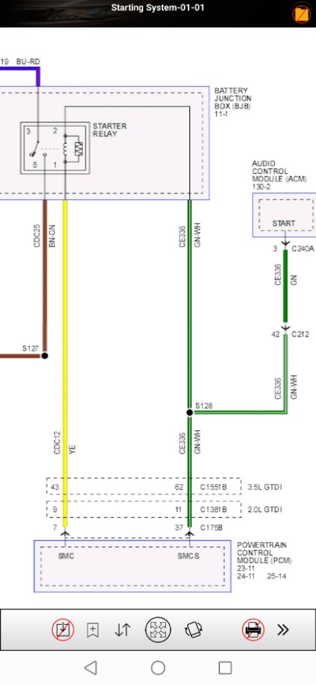
Hard to say as the diagram doesn't tell us everything.
You'll need a good description and operation or a test light to figure it out with the relay removed. I'm thinking the green is power when cranking and the yellow is ground, but I could be wrong.
Post this to my forum www.scannerdanner.com it's free to join and we can help there. Can't really offer this here on messenger my friend. Too many people asking for help to answer everyone
Don't be a parts changer!
Please Log in or Create an account to join the conversation.
- ScannerDanner
-
- Offline
- Administrator
-
- Religion says do, Jesus says done!
- Posts: 975
- Thank you received: 500
Pull the relay and connect a test light to ground and touch it on pins 1 and then 2 individually while cranking, then connect the test light to battery positive and do the same test, this will answer your questions for sure. At least on a working circuit.
Don't be a parts changer!
Please Log in or Create an account to join the conversation.
- Isaacs_motoring
-
Topic Author
- Offline
- New Member
-
- Posts: 16
- Thank you received: 0
Please Log in or Create an account to join the conversation.
- Isaacs_motoring
-
Topic Author
- Offline
- New Member
-
- Posts: 16
- Thank you received: 0
Please Log in or Create an account to join the conversation.
- Hardtopdr2
-
- Offline
- Platinum Member
-
- Posts: 853
- Thank you received: 150
Please Log in or Create an account to join the conversation.
- ScannerDanner
-
- Offline
- Administrator
-
- Religion says do, Jesus says done!
- Posts: 975
- Thank you received: 500
Great question! Someone has been paying attention. Love it! This is something you always have to ask yourself when a driver doesn't function as designed. The timing of when you install the test light and then also clearing codes and keeping an eye on current codes, are all things you should ALWAYS consider. You are on it my friend. In the case of a relay, I'm not sure that I've seen a lockout occur like we see on other outputs, but you never know.Thanks... I don't need to worry about the computer shutting down the circuit as a result of the relay taking out? If I do, I suppose I could put a voltmeter and see the momentary spike as I cycle the key on, off, and crank before the computer shuts it down, right?
Now to the case in hand. I'm assuming you have a no crank issue that you are trying to narrow down? Are there any anti-theft codes? Do you have the ability to look at data PIDs like gear position etc.?
BTW you can use your test light for the test you just described with the voltmeter. Install your test light as a jumper between those two pins and crank it. Just please, be SUPER careful that these two pins do NOT touch each other with whatever adapters you are going to use.
Don't be a parts changer!
Please Log in or Create an account to join the conversation.
- Isaacs_motoring
-
Topic Author
- Offline
- New Member
-
- Posts: 16
- Thank you received: 0
Please Log in or Create an account to join the conversation.
- Hardtopdr2
-
- Offline
- Platinum Member
-
- Posts: 853
- Thank you received: 150
Please Log in or Create an account to join the conversation.
- ScannerDanner
-
- Offline
- Administrator
-
- Religion says do, Jesus says done!
- Posts: 975
- Thank you received: 500
Time to start looking at all the inputs my friendNo anti theft codes... I installed a jumper wire in between the load side terminals and it cranked and ran. What I really think I'm missing is the ignition feed which I think is supplied by the pcm. That was why I asked the question about the diagram to begin with. Using a test light I found a feed which is hot all the time, finding the second feed (as a relay needs two powers to work) was the issue, both with ignition on and off.
Don't be a parts changer!
Please Log in or Create an account to join the conversation.
- Isaacs_motoring
-
Topic Author
- Offline
- New Member
-
- Posts: 16
- Thank you received: 0
Please Log in or Create an account to join the conversation.
- Hardtopdr2
-
- Offline
- Platinum Member
-
- Posts: 853
- Thank you received: 150
If you did check in crank position then you will need to look at the Gear selector position data, transmission range sensor data, ignition position data, wiring diagrams for the starting and charging circuit, ignition switch, pcm, TCM, gem module for where the starter command and disable is sent to pcm and confirm if it's getting a start signal, also test relay(ohm test both circuit sides of relay) to see if it is bad or swap a good one from another spot in fuse box in its place and see if it works. Sometimes it's the simplest problem that we miss a step and go down a rabbit hole.
Please Log in or Create an account to join the conversation.
- Isaacs_motoring
-
Topic Author
- Offline
- New Member
-
- Posts: 16
- Thank you received: 0
Please Log in or Create an account to join the conversation.
- Isaacs_motoring
-
Topic Author
- Offline
- New Member
-
- Posts: 16
- Thank you received: 0
Please Log in or Create an account to join the conversation.
- Isaacs_motoring
-
Topic Author
- Offline
- New Member
-
- Posts: 16
- Thank you received: 0
Please Log in or Create an account to join the conversation.
- jreardon
-
- Offline
- Platinum Member
-
- Posts: 521
- Thank you received: 198

Please Log in or Create an account to join the conversation.
- Isaacs_motoring
-
Topic Author
- Offline
- New Member
-
- Posts: 16
- Thank you received: 0
Please Log in or Create an account to join the conversation.
- jreardon
-
- Offline
- Platinum Member
-
- Posts: 521
- Thank you received: 198
B is body, E is Engine and T is transmission i think. So B, E and T. Crossing fingers, and b.e.t. ting this order is correct.

Please Log in or Create an account to join the conversation.