P0340 - CMPS Reference Voltage Issue
- derekj308
-
 Topic Author
- Offline
- New Member
-

- Posts: 9
- Thank you received: 0
Just joined the forum, been watching the ScannerDanner videos on YouTube for a few years now and I have learnt a lot. I'm in Victoria Australia, do my own repairs, used to own a 308 c.i. 1971 Holden HG Premier, got married, had 4 kids, now own a family wagon. Hmmm. It's not so bad, you can fit a few sheets of 4' x 8' plywood in it if you take the rear seats out
") .
.Relevant car specs are 2008 KIA VQ Grand Carnival EX (similar to Sedona?) 3.8L engine code G6DA, ECU code C42, B1 and B2 CMPS only on inlets.
My problem is with a P0340 DTC. Not so long ago I was driving home and the car went into limp mode and luckily I made it hope, limping
") .
.The symptoms now are are terrible idle, misfiring and hard to start with the P0340 code not going away after clearing with OBD2 tool. I haven't driven it since. It wouldn't get far.
I read up on P0340 and many said not to blindly change the CMPS so I did some simple voltage tests on in circuit and out of circuit back probed connectors for both B1 and B2 CMPS. In circuit and with key ON condition I found that the supply voltage was 5V, the ground was 0V but the signal voltage was 1.2V on both CMPS. I thought it was supposed to be 0V or 5V dependent on the reluctor wheel position with the sensor. I have posted a similar question over at KIA Forums and a kind person (shout out to bopbo) measured the signal voltage on his 2006 Carnival/Sedona (its Gen 2 like my 2008) and he measured 5V. I know now something is wrong with the reference voltage circuit, hence the P0340 DTC.
Next I did circuit test of just the connectors, i.e. both connectors were disconnected from B1 and B2 CMPS and remeasured voltages. Supply at 5V, ground at 0V but now the signal voltage is 5V on both connectors. So now I plug one connector back in and BOTH signal voltages drop back to 1.2V. I try vice versa, i.e. I pull out that plug and plug the other CMPS plug back in and same result, BOTH signal voltages are at 1.2V.
It seems the act of plugging in either CMPS connector drags the signal voltage down to 1.2V.
I also found some bad wiring to the CKPS right at the connector, I am assuming it was from an oil leak. I repaired the wiring and measured the resistance back to the unplugged connector on the ECM and it was the same as the out of circuit resistance of the CKPS so I assume that cannot be contributing to the P0340, now at least. It may have kick stated this P0340 issue, I am unsure if it is related.
I made a simple oscilloscope with an Arduino and some PC software and I was able to see the CMPS signal with the car running and it looked like it was toggling between 'its' high and low of around an average of 1.2V high and 0 low. There was a LOT of noise on the signal but the system I am using was basically an antenna so whether or not the noise was a symptom of an underlying problem I really don't know. While I was in there I also measured the supply voltage and it was 5V and had some noise but nothing like the signal wire.
I'm new to diagnostics and having fun learning but it is time for me to put my hand up and ask the pros for some guidance.
Any suggestions on what tests to perform next. I have a DMM and a poverty single channel featureless oscilloscope.
Thanks in advance,
derekj308
Please Log in or Create an account to join the conversation.
- derekj308
-
Topic Author
- Offline
- New Member
-
- Posts: 9
- Thank you received: 0
I did some tests suggested by kiaguy002 over at KIA Forums and found 0 ohms resistance on each of the 6 wires between the ECM plug B disconnected from the ECM and the disconnected CMPS plugs. I also did a resistance test with the ECM plug B and ECM plug A connected to the ECM and both CMPS plugs were disconnected. What I found was the following;
0 ohms - Brown (GND) of CMPS B2 to Black (GND) of CMPS B1
3.3k ohms - Brown (GND) of CMPS B2 to Green (SIG) of CMPS B1
3.95k ohms - Brown (GND) of CMPS B2 to Pink (+5V) of CMPS B1
3.3k ohms - Brown (GND) of CMPS B2 to Grey (SIG) of CMPS B2
810 ohms - Brown (GND) of CMPS B2 to Pink (+5V) of CMPS B2
There is a discrepancy on the +5V line, my guess is the 810 ohms on CMPS B2 is the culprit. I measured the resistance directly on the pins of the ECM to ground to narrow it down to either wiring or internal to the ECM.
I think I'm on to something now. I can make the 810 ohms change to 3.6k ohms. I measured the resistance directly on the pins of the ECM and it was 810 ohms so naturally I thought it MUST be the ECM. Plug A of the ECM was still connected so I thought I'll test with plug A disconnected and then it HAS to be the ECM. I tested again with plug A off and the resistance was 3.6k ohms. Huhhh? Not the ECM it would seem.
I then started to try and isolate the fault on the circuit that is part of plug A of the ECM. In short I have got it down to the circuit which consists of;
plug A of the ECM
top two plugs of the fuse box
the fuse box
I am able to disconnect all of the three underside plugs of the fuse box so they can be ruled out.
I'm getting closer
Please Log in or Create an account to join the conversation.
- derekj308
-
Topic Author
- Offline
- New Member
-
- Posts: 9
- Thank you received: 0

I'm just trying to get some guidance, from my perspective at least, on a hard diagnosis problem.
Anyhow, I'll keep trying and when I do find the solution, and I will, I'll post it back here for reference.
Please Log in or Create an account to join the conversation.
- Tyler
-

- Offline
- Moderator
-

- Full time HACK since 2012
- Posts: 6124
- Thank you received: 1541
But I can tell you what stands out to me in your testing. For what it's worth, I've looked at the wiring diagram on an '08 Sedona. All the wiring I've looked at so far matches what you've found on your Grand Carnival.I know you don't like the resistance of the B2 5V circuit, and I understand why. For me, this is what stands out:
3.3k ohms - Brown (GND) of CMPS B2 to Green (SIG) of CMPS B1
3.3k ohms - Brown (GND) of CMPS B2 to Grey (SIG) of CMPS B2
I can't say I've measured resistance from a Hall effect signal circuit to sensor ground before. :lol: But this doesn't sound like enough resistance. It doesn't take much, in my experience. I may go take some measurements on my cars for giggles.
The problem is, even if that 3300 ohms is a resistive short, why isn't it pulling that voltage down all the time? Why only when a CMP sensor is connected?
I think I'm on to something now. I can make the 810 ohms change to 3.6k ohms. I measured the resistance directly on the pins of the ECM and it was 810 ohms so naturally I thought it MUST be the ECM. Plug A of the ECM was still connected so I thought I'll test with plug A disconnected and then it HAS to be the ECM. I tested again with plug A off and the resistance was 3.6k ohms. Huhhh? Not the ECM it would seem.
Not trying to be a hater, but I think you're going down a rabbit hole. I don't know what all is in ECM Plug A (or C01-1 according to the OE diagram). But I bet it's a TON of different circuits! We don't know exactly what you're changing, or how the ECM is wired internally. You measured the 5V circuit at the CMPs with the engine running and found 5V. That tells me the ECM and the circuit are able to keep up with demand.
Maybe I'm way off. Thinking about this is making my head hurt. :lol: I need a white board to sketch this stuff out...
Please Log in or Create an account to join the conversation.
- Matt T
-
- Offline
- Platinum Member
-

- Posts: 751
- Thank you received: 276
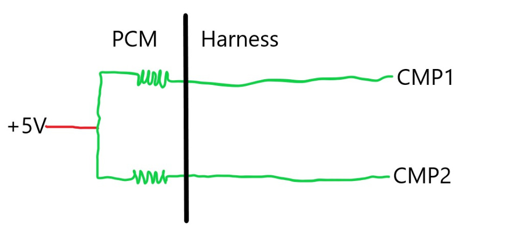
One other test just to confirm would be unplugging both CMPs and hooking up a DMM across one of thems signal wire and sensor ground. Then short the other signal wire to sensor ground and see what it does to the other signal wires voltage.....
Please Log in or Create an account to join the conversation.
- derekj308
-
Topic Author
- Offline
- New Member
-
- Posts: 9
- Thank you received: 0
Thanks for the replies. I need all the help I can get. @Tyler funny you should say say rabbit hole. I was thinking the same thing and I am way down it. @ Matt I did a bit of reading on pull down circuits and this is what I assumed was happening as per your diagram. The digital circuit in the PCM sees 5V when the signal to sensor ground is O/C and is pulled to 0V when the CMPS circuit closes. I also assumed that the 5V regulator circuit inside the PCM must be getting pulled down hard to pull the signal voltage from what should toggle between 0 and 5V to toggling between 0 to 1.2V. I have been busy in there with isolating circuits so getting back to a position of testing voltages isn't 5 minutes work
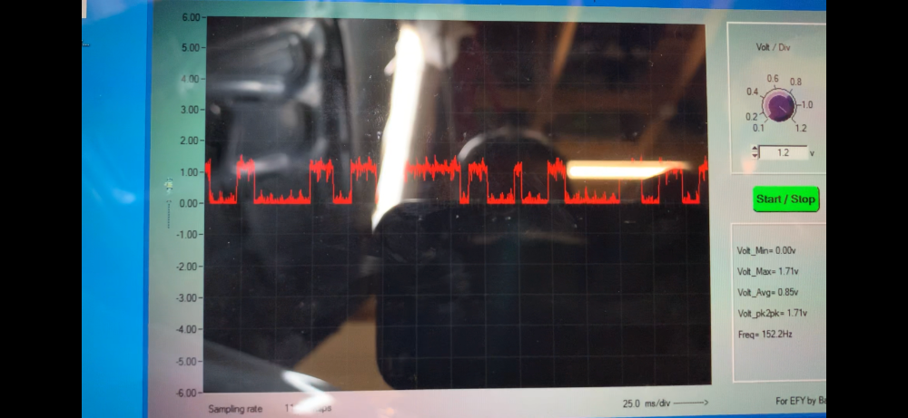
.What do you guys think about the excessive noise on the 1.2V signal? Is that something that might narrow down the type of fault? I was able to take a snap shot from a video I took, see picture below.
The stage I am at is I have done a resistance test to ground of all of the pins of connector A (CO1-1) and found that only one pin, pin #63 on C01-1 gives a resistance. My logic is that connecting C01-1 to the PCM causes the resistance across pins #15 and #17 of C01-2 PCM side to drop from 3.6k ohms to 810 ohms. I did these measurements with the key off and no battery present. It leads me to believe that the fault is tied to the circuit/s between pin #63 and ground. I isolated the Front Area module (FAM) from the three connectors under the FAM and probed the FAM until I found a hit on pin #36 of BCM-FE FAM side (pg.16 of attached file) and found the resistance of practically 0. When I connect BCM-FE the resistance is around 4.3k ohms but I have measured 4.5k and 4.8k in previous tests. Pin #36 of BCM-FE follows back to the MIL lamp circuit and from what I can interpret, pin #36 is a ground to the PCM for the MIL lamp to function.
Assuming I am on the right path, the bit I am confused with now is, as Tyler says, do I go left or do I go right? Do I keep searching for a rubbed out wire in the loom via pin #36 towards the instrument cluster or can I create a list of suspects to test based on the instrument cluster circuit shown on pg.70?
Thanks again guys for reaching out.
Please Log in or Create an account to join the conversation.
- derekj308
-
Topic Author
- Offline
- New Member
-
- Posts: 9
- Thank you received: 0
I did measure the resistance of the signal to ground terminals of B1 and B2 to their respective ground terminals and both measured 2.4k ohms. I also measured the resistance of signal to power, B1 and B2 both O/C and same for power to ground both O/C. I know it sounds late in the game but shouldn't the CMPS signal be either short to ground or O/C, i.e., a switch :silly:, so the logic circuit in the PCM sees 0V or 5V respectively assuming the PCM has a pull down resistor? My understanding / assumption is the voltage measured in the PCM is after the pull down resistor. Any additional resistance in the signal circuit creates a split of the reference voltage and would therefore cause the PCM measured signal voltage to be either 5V or greater than 0V depending on the value of the pull down resistor and the 2.4k ohm resistor in series.
I don't think I understand the inner workings of a three pin Hall Effect sensor.

When I first got the error I swapped the CMPS B1 to B2 and vice versa to see if I could push the DTC to show a different code. Since nothing changed I automatically assumed both CMPS were good. I have also tested them by moving a socket across the sensor and I can see the signal voltage toggling from 1.2V to 0V when I use the CMPS plugs so all that really proves is that both sensors can pull to ground when active but can they both simulate O/C with a high resistance.
All that said I can't get past the fact that I can change the 3.6k ohms to 810 ohms by plugging the A connector in on the PCM.
Brain pain.
Please Log in or Create an account to join the conversation.
- Tyler
-
- Offline
- Moderator
-
- Full time HACK since 2012
- Posts: 6124
- Thank you received: 1541
What do you guys think about the excessive noise on the 1.2V signal? Is that something that might narrow down the type of fault? I was able to take a snap shot from a video I took, see picture below.
Nah, that looks like typical noise to me.
Like you said earlier, the scope leads will pick up all kinds of stuff underhood. I wouldn't sweat it.Borrowing the sketch Matt came up with earlier, I think this is what's actually happening inside your ECM:
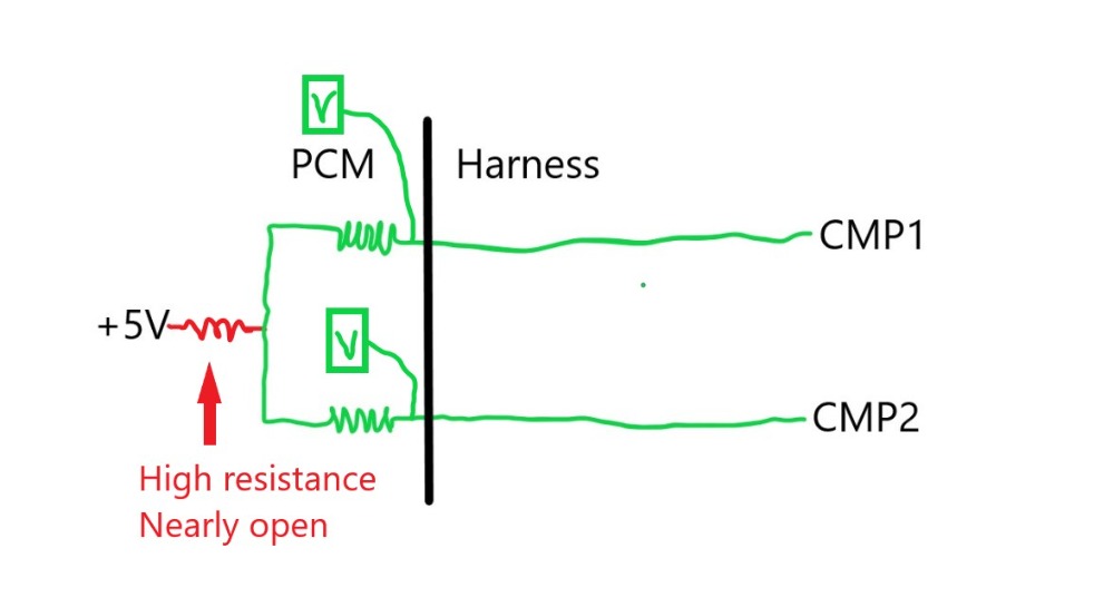
With this failure, almost any load on either circuit will result in the signal bias getting pulled low.
Now that I'm thinking about it, are there any other sensors on your Kia that also have low 5V reference feeds? The MAP or the A/C pressure transducer would probably be the easiest two to check.
Please Log in or Create an account to join the conversation.
- derekj308
-
Topic Author
- Offline
- New Member
-
- Posts: 9
- Thank you received: 0
@Tyler, good idea. When I get everything back to a connected state where I can power up again (why did I just think of Bubble Bobble :lol:) I'll do a run a round on sensors with 5V refs and I'll do the test Matt suggested also. When you mentioned A/C my spidey senses tingled and I remember I had a severe valve cover leak which oiled up the connector that goes to the mag clutch on the A/C pump. Better get down there and have a look.
I am relieved that you think the signal noise is not a symptom of something else.
BTW before I went hunting for resistance gremlins and unplugging connectors I did do some voltage checks on the ground wires for both B1 and B2 CMPS. Ground voltage for the earth lead closest to the sensors (attached to B2 valve cover) was 4mV and at the sensors the ground voltage was ~9mV. I think I remember Tyler saying in one of his videos that voltage under 10mV on a ground was good so I kept looking else where for suspects.
Please Log in or Create an account to join the conversation.
- Matt T
-
- Offline
- Platinum Member
-
- Posts: 751
- Thank you received: 276
derekj308 wrote: I did measure the resistance of the signal to ground terminals of B1 and B2 to their respective ground terminals and both measured 2.4k ohms. I also measured the resistance of signal to power, B1 and B2 both O/C and same for power to ground both O/C. I know it sounds late in the game but shouldn't the CMPS signal be either short to ground or O/C, i.e., a switch :silly:, so the logic circuit in the PCM sees 0V or 5V respectively assuming the PCM has a pull down resistor? My understanding / assumption is the voltage measured in the PCM is after the pull down resistor. Any additional resistance in the signal circuit creates a split of the reference voltage and would therefore cause the PCM measured signal voltage to be either 5V or greater than 0V depending on the value of the pull down resistor and the 2.4k ohm resistor in series.
Electronic "switches" don't always go fully open circuit like mechanical switches do. They'll show some continuity with a DMM and also leak a small amount of current in their off state powered up.
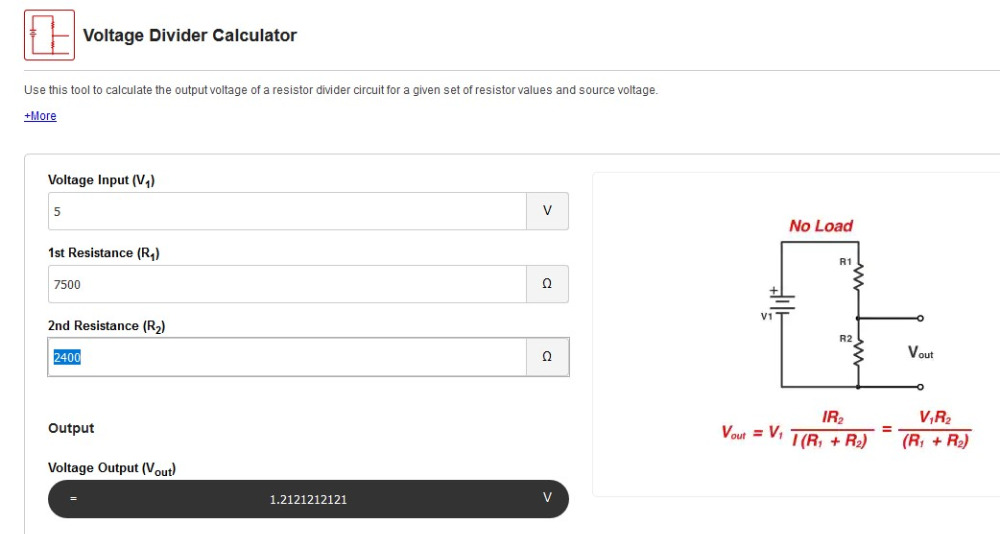
2.4K does sound too low but that cold resistance doesn't necessarily mean that's what the sensor will do powered up. When you get everything back together you could try grounding the signal wires with some different resistors to see what they do to the signal voltage. I plugged 2.4K 1.2V into a calculator and it works out to 7.5K of resistance inside the PCM. But really need to re-do the measurement with a known resistance.
www.digikey.com/en/resources/conversion-...ator-voltage-divider
Please Log in or Create an account to join the conversation.
- derekj308
-
Topic Author
- Offline
- New Member
-
- Posts: 9
- Thank you received: 0
Good news, its running! Both of my cam sensors were faulty. WTF! A very kind gentleman (shout out to bobpo again) lent me two cam sensors off another KIA Carnival/Sedona and they work fine. I can now be confident in purchasing new sensors.
The key here was the resistance values on the ref voltage signal to signal ground on my cam sensors was the indicator that both of the sensors were bad, I just didn't know it at the time. What threw me was that both of them were actually bad. I made the mistake of assuming (a.k.a the mother of all f ups) that since the resistances of both sensors were consistent then they MUST be ok. I had no point of reference so I can understand why I took this path. In hindsight if I had known that the resistance on the ref voltage signal to ground was supposed to be very high i.e. in the M ohms range I could have saved myself much mental pain and wasted time. It makes perfect sense that in a pull down circuit, any resistance added in after the 'voltmeter' in the ECM will create a voltage split so in order to ensure the signal voltage high value stays at the reference voltage, the resistance of the sensor signal to ground circuit must be effectively O/C i.e. a very high resistance compared with the internal resistance on the ref voltage circuit in the ECM.
Another take away here was the resistance approach I was using with the connector A (C01-1) and connector B (C01-2). It did not serve me well and directed me straight down the rabbit hole. I wasted a lot of time due to this. Fortunately for me I don't just tear parts and wiring out ad-hoc so the worst I ended up with was having to re-cover small parts on the under hood loom in a very localized area where I suspected oil and battery acid may have been. There are a number of components that were directly responsible for me seeing the change in resistance across pins #15 and 17. The A/C pressure sensor, the throttle position sensor and the accelerator position sensor all contributed to the drop from 3.6k ohms to 810 ohms when I connected connector A to the ECM and observed the resistance across #15 and #17. All of these parts have variable resistors in them and effected the resistance I was measuring. This is not to say that in general, every part with a variable resistor will effect the resistance measured across some combination of pins in an ECM. All I am saying is that it did not provide me with useful information to diagnose my error.
After I put those cam sensors in it started but then I had a P0302 'Cylinder 2 Misfire Detected' and a P0341 'Camshaft Position Sensor "A" Circuit Range/Performance' error. Luckily I had some spare coil packs and plugs so I swapped out cylinder 2 coil pack and spark plug and voila its running again.
Thanks to Tyler and Matt for your assistance. This has been by far the hardest car related issue I have had to solve BUT I learnt so much in so little time and I am now very familiar with my under hood components, reading circuit diagrams, and I want to learn more so I am prepared for next time.
Cheers
derekj308
Please Log in or Create an account to join the conversation.
- derekj308
-
Topic Author
- Offline
- New Member
-
- Posts: 9
- Thank you received: 0
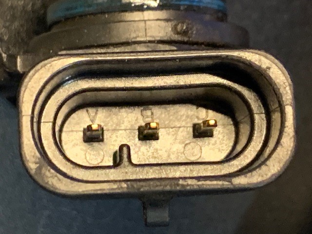
C pin is 5V supply
B pin is signal ground
A pin is 5V reference signal
all pins are fed directly from the ECM
A to B 1.2M Ohms
B to A no reading any scale (no idea why this isn't the same as A to B, its a resistance, right?)
A to C 1.5M Ohms
C to A no reading any scale
B to C 1.2M Ohms
C to B 1.2M Ohms
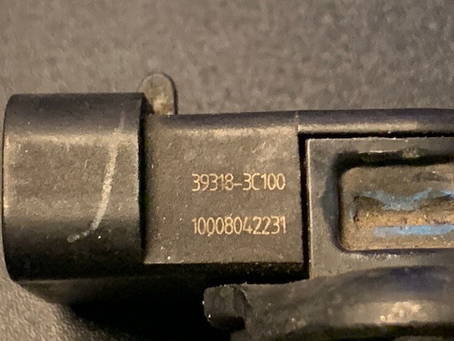
KIA Sensor P/N is 39318-3C100 and there is another number under it 10008042231, I am assuming it is a manufacturing tracing number.
BTW I just bought the SD eBook
")
Cheers
derekj308
Please Log in or Create an account to join the conversation.
- Matt T
-
- Offline
- Platinum Member
-
- Posts: 751
- Thank you received: 276
derekj308 wrote: What threw me was that both of them were actually bad.
Yeah it seems unlikely they both failed at the same time. Was the money light on before this happened? Would probably set a code, but run fine, with one sensor bad. Then when the second failed it'd go into limp home.
Your 1.x megohms one way and O/L the other readings are probably because of a diode in the circuit. The diode blocks the DC current from your DMM in one direction, which causes the O/L reading, but allows it to pass in the other.
Please Log in or Create an account to join the conversation.
- Tyler
-
- Offline
- Moderator
-
- Full time HACK since 2012
- Posts: 6124
- Thank you received: 1541
derekj308 wrote: Good news, its running! Both of my cam sensors were faulty. WTF! A very kind gentleman (shout out to bobpo again) lent me two cam sensors off another KIA Carnival/Sedona and they work fine. I can now be confident in purchasing new sensors.
Really? :blink: That's... incredible. I don't doubt your fix! I'm just not happy with the why.
It makes perfect sense that in a pull down circuit, any resistance added in after the 'voltmeter' in the ECM will create a voltage split so in order to ensure the signal voltage high value stays at the reference voltage, the resistance of the sensor signal to ground circuit must be effectively O/C i.e. a very high resistance compared with the internal resistance on the ref voltage circuit in the ECM.
I think you're exactly right. In my head, I had made the mistake of thinking that potentiometers and Hall sensors will have the same kind of resistance to ground on the sensor circuit. :blush: 2.4K ohms to ground on a pressure sensor isn't unreasonable, in my experience, so I didn't think much of it. Stupid mistake.
Plus, like you said, what are the chances that they'll both measure out to 2.4K? :silly:
Please Log in or Create an account to join the conversation.
- derekj308
-
Topic Author
- Offline
- New Member
-
- Posts: 9
- Thank you received: 0
@Tyler I'm still a little nervous cause I don't really know if its fixed. I hope Matt is right that one had failed and when the other one failed that's when the P0340 DTC came up. It makes sense so I'll take that bet. Weird that when that was fixed, magically the P0341 and P0302 came on. When that happened I said under my breathe, "Lord give me strength!" I was so relieved when the coil pack and plug swap on cylinder 2 fixed the issues.
@Matt thanks for the diode reference. That's what it will be.
I have had ongoing issues with running rich (stinky exhaust, poor fuel economy) and all ever got from DTCs was O2 Sensor related DTCs, never had any cam sensor DTCs.
Thanks again guys for the support. At the very least we have left some breadcrumbs for others to follow.
Please Log in or Create an account to join the conversation.