[FIXED] IGT1 The plain and simple fact.
- Otbrecords
-
 Topic Author
- Offline
- Senior Member
-

- Posts: 52
- Thank you received: 13

Please Log in or Create an account to join the conversation.
- cj1
-
- Offline
- Premium Member
-

- Posts: 87
- Thank you received: 12
Let us know the outcome.
Please Log in or Create an account to join the conversation.
- VegasJAK
-

- Offline
- Platinum Member
-

- Silencing the Parts Cannon
- Posts: 566
- Thank you received: 140
1. Engine was running fine prior to any work being done by the brother.
2. Brother only replaced the timing belt.
3. Brother did not remove the cam or crank gears.
4. Brother removed the crank pulley.
5. Brother did not remove cam or crank sensors.
6. Brother did not alter the coils, igniters, wires or ECM.
7. Engine did not have low vacuum prior to repair.
Results of repair;
1. Car runs but has misfire on #1 & #4 cylinders.
2. Engine has low vacuum.
3. lGT1 has no signal.
4. lGT1 controls cylinders 1&4.
Additional repairs or test you have done.
1. Replaced igniter and ECM.
2. Swapped coils and plugs.
3. Tested powers and grounds.
4. Used an alternate wire for the lGT1.
5. Rechecked timing.
6. All above did not correct the problem.
If all that was done was to replace the timing belt and that altered the engine condition, we can directly infer the initial repair caused the problem.
Timing is critical to engine operation. If the timing is off just a little it can cause the low vacuum, engine misfire and related codes. With this engine it may be causing the lGT1 condition.
This all points to the repair and timing. I would go back and tear down everything to the point of the belt replacement. I would talk to the brother and find out every step he did. You assume he did it correct, but it is apparent something was done wrong resulting in the current condition. Their is no reason for the current misfire as no condition existed prior to the repair.
Liminy Snigett... an unfortunate chain of events...
"an open mind let's knowledge flow in and wisdom flow out for a man who has neither never listens to those who have both".
Please Log in or Create an account to join the conversation.
- Otbrecords
-
Topic Author
- Offline
- Senior Member
-
- Posts: 52
- Thank you received: 13
Please Log in or Create an account to join the conversation.
- VegasJAK
-
- Offline
- Platinum Member
-
- Silencing the Parts Cannon
- Posts: 566
- Thank you received: 140
Each IGT circuit has four wires... 12v, 5v, a ground and signal IGF wire (B-Y to the ECM). The 12v supplies power to transistor in the coil, the 5v is from the ECM to a transistor in the igniter. The 5v is controlled by the cam and crank sensors via the ECM through grounding that turns on and off the transistor for the igniter which then lets the coil fire. The IGF sends an on off signal back to the ECM letting it know that the coil has fired.
Each coil/igniter has a common ground, 12v, 5v and IGF. If IGT 2&3 are working then one of the common connection to IGT1 has been compromised. I would look closely at the IGF wire.
You had brief circuit integrity then failure. Have you returned those to the other guy, are they working?
"an open mind let's knowledge flow in and wisdom flow out for a man who has neither never listens to those who have both".
Please Log in or Create an account to join the conversation.
- Otbrecords
-
Topic Author
- Offline
- Senior Member
-
- Posts: 52
- Thank you received: 13
3 IGT wires come into the ignitor from ECU and 3 wires go out of ignitor to the coils. Now please correct me if I'm wrong. The remaining 4 wires are the common wires shared by the 3 IGT wires. The coils don't have ignitors built in, I have just coils. The 4 remaining wires are 12v, 5, ground, & IGF. So if IGT#2 & #3 are pulsing @ 3.9v which in turn fire cylinders 2,3,5,& 6...then possibly those 4 common wires aren't the issues? You've got me thinking now. I performed a pull-up test on IGT1 at ignitor and at ECU. Both places fired corresponding cylinder plugs. (#1) I tested cam/crank sensors (not under load) which were good. I assumed since IGT2 & IGT3 were working that it wasn't an input problem. Could it be a sensor failing under load? Doesn't make sense to me. BUT brother might have messed with or something happened to crank gear and or reluctor ring. ScannerJohn could you tell me if some kind of issue with either, especially the reluctor ring could cause a IGT no signal? Thank you sir for the conversation.


Please Log in or Create an account to join the conversation.
- VegasJAK
-
- Offline
- Platinum Member
-
- Silencing the Parts Cannon
- Posts: 566
- Thank you received: 140
A single igniter works the same, the common connections are in the unit. The 3.9v has me concerned. Should be a 5v on off signal. The IGF circuit should be the same. Unplug one coil at a time and see if you get a 5v signal. I'm thinking the 3.9 is pulling down the IGT1 circuit. You used a good known ECM and igniter and still had the same readings, can you check voltage on your friends system and compare readings.
The crank and cam sensors supply a chip in the ECM with a on off signal that powers a transistor to power the each igniter and coil circuit. If the sensors were bad IGT2&3 would not be working.
The low vacuum can be the result of cam and crank mistiming. Cant figure why brother would have taken off the cam gear for belt change. If he moved the crank position and did not align that can be a factor.
I keep going back to the same reasoning... if it ran before the belt change and all that was done was a belt change, how can that relate to the IGT1 problem. Timing, cam and crank. If you are able to scope the engine you could determine if timing was correct without tearing down the engine. The timing must be off just a little to allow 2&3 to fire but not 1. You can manually fire 1 so the circuit is good forward of the ECM.
"an open mind let's knowledge flow in and wisdom flow out for a man who has neither never listens to those who have both".
Please Log in or Create an account to join the conversation.
- Otbrecords
-
Topic Author
- Offline
- Senior Member
-
- Posts: 52
- Thank you received: 13
Please Log in or Create an account to join the conversation.
- Otbrecords
-
Topic Author
- Offline
- Senior Member
-
- Posts: 52
- Thank you received: 13
Please Log in or Create an account to join the conversation.
- Otbrecords
-
Topic Author
- Offline
- Senior Member
-
- Posts: 52
- Thank you received: 13
Please Log in or Create an account to join the conversation.
- VegasJAK
-
- Offline
- Platinum Member
-
- Silencing the Parts Cannon
- Posts: 566
- Thank you received: 140
Do the tests on page 2 and let me know the results. You have a scope so the waveform on IGT1,2,3 and IGF will tell all. Back probe each pin at ECM. Use 4 channels and set scope to 20msec and 10v.
"an open mind let's knowledge flow in and wisdom flow out for a man who has neither never listens to those who have both".
Please Log in or Create an account to join the conversation.
- Otbrecords
-
Topic Author
- Offline
- Senior Member
-
- Posts: 52
- Thank you received: 13
Please Log in or Create an account to join the conversation.
- Cheryl
-
- Offline
- Platinum Member
-
- Posts: 1216
- Thank you received: 215
Please Log in or Create an account to join the conversation.
- VegasJAK
-
- Offline
- Platinum Member
-
- Silencing the Parts Cannon
- Posts: 566
- Thank you received: 140
to the question of sensor or wires as part of testing for ECM;
When you do testing for a specific problem such as a code#, in this case the P0351 as that is the procedure you were using, the procedure is based on what engineers have deemed appropriate for that component only. They include small nuggets in footnotes that directs you to other procedures to check other related components. A novice and many advanced DIYers miss this. Its frustrating to say the least. Inputs basics for the computer are the cam and crank sensors.
Sensors are still a question;
In this case your inputs are verified as the injectors are firing, they work off the cam and crank signals via the ECM. I questioned before but you did not reply, the tach, is it working normal, abnormal or not at all. The tach is part of the same circuit as cam and crank and IGT. If the cam and crank signals were absent, the engine would not start.
Timing belt placement;
If the cam and crank are not aligned "timed" correctly the signal from the sensors will be reported to the ECM at the wrong time and the engine will no run or run poorly, not to mention internal damage to the engine in extreme cases. In the engine you have with overhead cams, one on each side, the two cams have to be timed together then timed to the crank. Its not that easy and even an experienced mechanic has done it wrong.
page 2 checking for opens or shorts;
Yes, both.
Just noticed, you say you have 12v on the IGF circuit... that's a 5v circuit. I have to check to make sure.
I can do it again;
You gave values for each IGT. The procedure was for an accumulative reading, but in the long run it does not matter as you have no signal from IGT1. The procedure is to point to a coil or igniter problem. The scope is great, it shows the wave forms and actual values where a DVOM only shows an average value in waves forms. In this case, IGT1 will show no value, but it could show a low value that the DVOM could not read. This would indicate a short.
Put truck back together;
The ECM is the problem in that you're not getting a signal from IGT1. I'm very interested in knowing if the returned ECM works. If it does then your system is pulling down that signal somewhere, maybe that 12v IGF. If its not working, your system is shorting out the IGT1. But why only IGT1 and not 2&3. Maybe a Toyota design fail safe not to blow the entire ECM (limp mode)
Your Toyota works off of three IGT's. In your case, two are working one is not. All three work off the same inputs. Those inputs control transistors for each IGT circuit that control each coil.
I wrestle with the fact one transistor is not working and why. Other than just being an old or bad transistor what caused the failure and why the alternate ECM suffered the same fate, if it did. And how this relates to the timing belt change.
All I can give you. Hopefully, someone with more knowledge can chime in and give more insight.
Update: IGF signal voltage should be 4.5 to 5.5 volts
So more info on the IGF signal. The IGF signal is generated each time an igniter/coil event occurs by an igniter and is sent to the ECM to confirm ignition. The ECM receives input from the crank sensor as to the next cylinder in the firing order and activates the corresponding IGT. If the ECM does not receive an IGF confirmation signal from an igniter within 9 firing cycles, the ECM shuts down the injectors for that coil. This stops the flow of fuel and prevents unburned fuel from entering the CAT.
You asked if the ECM shuts down an IGT. No, it shuts down the fuel injector for the non responsive coil on that IGT. This bring me back to the crank gear as the crank sensor feeds the ECM the signal as to crank position for cylinder firing.
"an open mind let's knowledge flow in and wisdom flow out for a man who has neither never listens to those who have both".
Please Log in or Create an account to join the conversation.
- Otbrecords
-
Topic Author
- Offline
- Senior Member
-
- Posts: 52
- Thank you received: 13
The voltage on IGF was 5v or there abouts and not 12v. I wrote that wrong. Also sorry for not answering your question about the tachometer, I some how missed that. Yes at start up the tach bounces before registering RPM. I will check to see what's on the wire still. A good spot to examine.
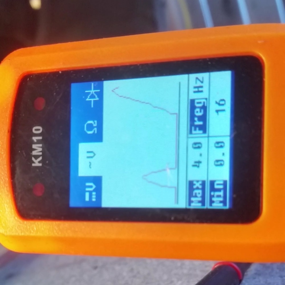
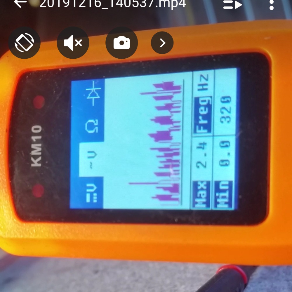
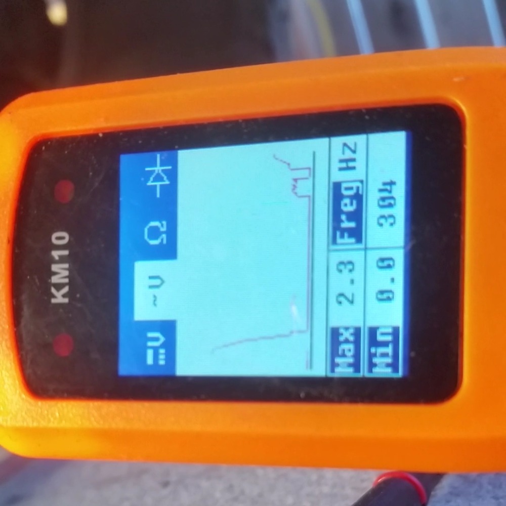
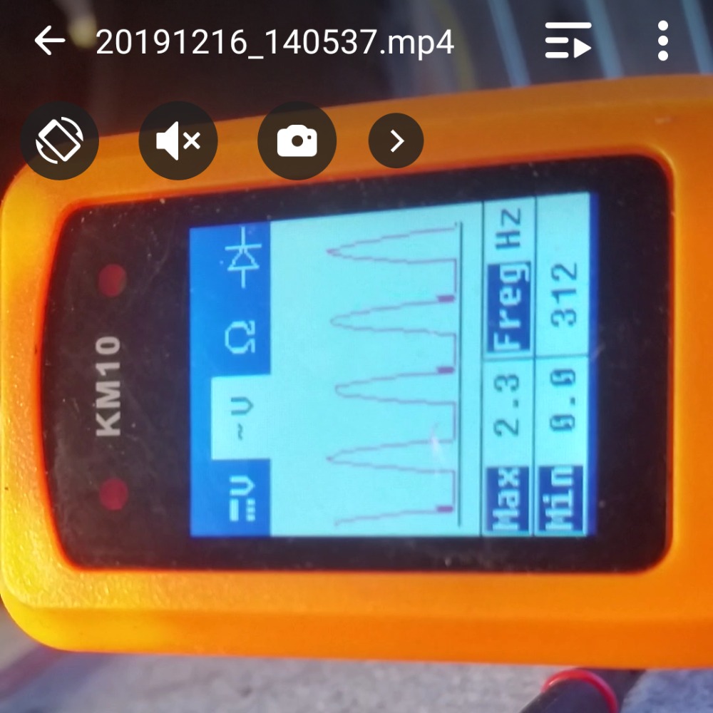
Brother returned second ECU and I installed the original ECU last night. It exhibits the same symptoms as before, as same as the second ECU did. Afterwards I attached my generic Power Probe that has a signal wave analyzer. The time duration is really short in what it shows you but it was enough. Pulled out my oscilloscope today and tried to get it working before I was off to work but with no luck. I quickly hooked up my Power Probe again and recorded with my phone. I back probed crankshaft sensor signal wire using a tpin, attached a wire to it to gain some separation from the moving belts, and rap the bare wires on the other end around the probe. Hoping that use of a wire lead like that wasn't causing the "scope" to show falsely. So this is the same Power Probe used to view the good square single waves on IGT2 & IGT3. I attached screenshot from the video and a zip file with a video in it. Interested to know your thoughts.

Please Log in or Create an account to join the conversation.
- Otbrecords
-
Topic Author
- Offline
- Senior Member
-
- Posts: 52
- Thank you received: 13
Please Log in or Create an account to join the conversation.
- VegasJAK
-
- Offline
- Platinum Member
-
- Silencing the Parts Cannon
- Posts: 566
- Thank you received: 140
What I'm looking for is a missing signal. Should have 11 signals the same then the pattern starts over again. If you have a missing or distorted signal, I believe this would be the #1 crank signal for IGT1. This suggest to me that the crank gear may be damaged. This would be consistent with working before timing belt repair and not after.
"an open mind let's knowledge flow in and wisdom flow out for a man who has neither never listens to those who have both".
Please Log in or Create an account to join the conversation.
- Otbrecords
-
Topic Author
- Offline
- Senior Member
-
- Posts: 52
- Thank you received: 13
I was a little heated but what can one do? It definitely reminds you to never trust the customer. Not an actual photo of my pulley gear
Please Log in or Create an account to join the conversation.
- VegasJAK
-
- Offline
- Platinum Member
-
- Silencing the Parts Cannon
- Posts: 566
- Thank you received: 140
the repair supports the crank waveform and all other testing done.
"an open mind let's knowledge flow in and wisdom flow out for a man who has neither never listens to those who have both".
Please Log in or Create an account to join the conversation.
- Noah
-

- Offline
- Moderator
-

- Posts: 5042
- Thank you received: 1120
Having the whole story from start to finish helps make this forum a great resource for anyone who needs help.
Please Log in or Create an account to join the conversation.