2003 Cadillac CTS 3.2 V6 automatic with wiring problems at the MAF and the ECM grounds- P0103 P0118
- Marti
-
 Topic Author
- Offline
- Premium Member
-

- Posts: 137
- Thank you received: 8
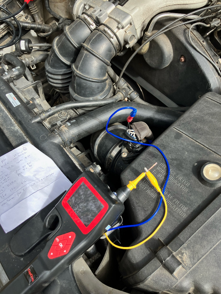
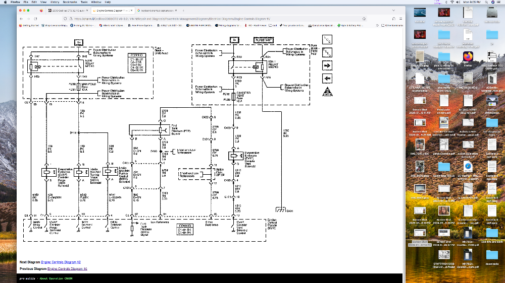
Pin-out for connector 1 (C1) at the Powertrain Control Module (PCM). I need the circuit for pin 39 at this connector. I also need to verify that MAF Pin 4 (labeled low reference on a wiring diagram I saw) is normally at 5 volts as I am measuring, and not supposed to be at ground voltage on this tan wire.
In 2022 I was on this forum and got this car running but I had to cut (near the PCM) the tan wire to C1, Pin 26 and ground it to the engine block in order for the car to start. I want to fix the problems with the ground to the MAF and figure out the circuit for the tan wire I cut.
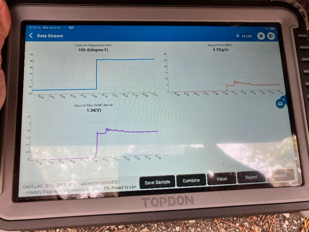
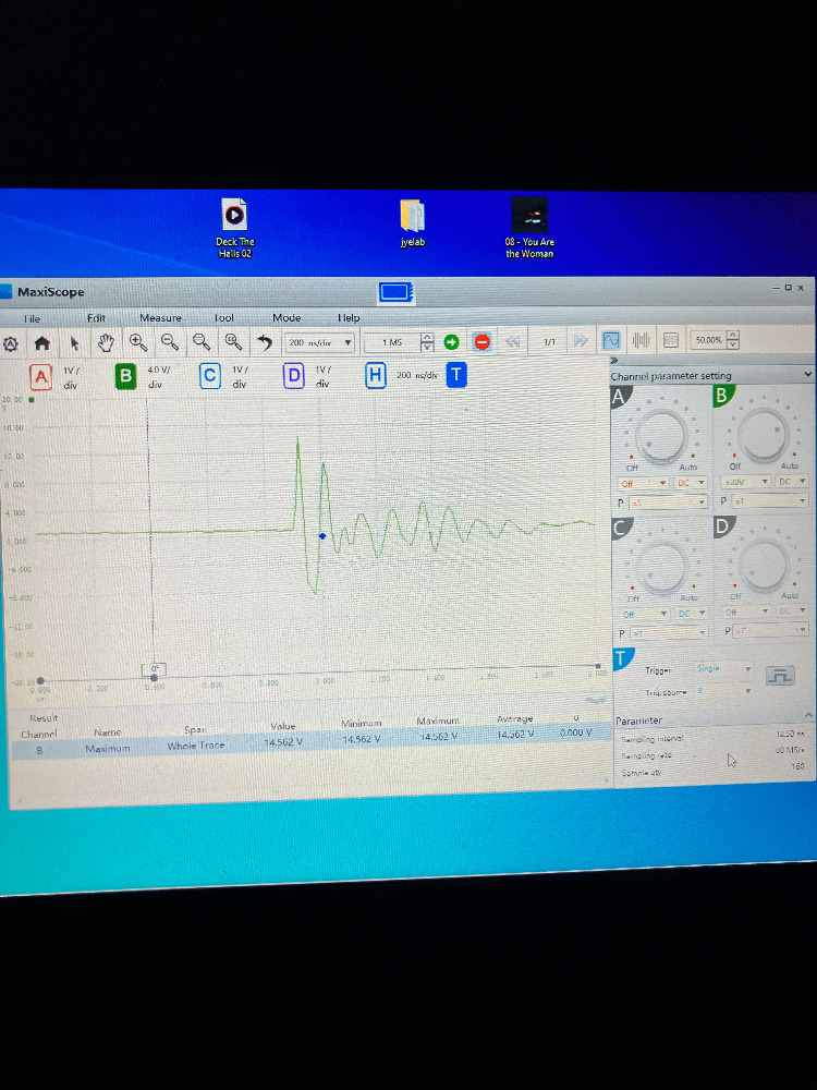
Attachments: The second image shows the MAF/IAT sensor first unplugged (low readings), then plugged in and reads just over 4 g/s of air into the engine
Marti
Please Log in or Create an account to join the conversation.
- Marti
-
Topic Author
- Offline
- Premium Member
-
- Posts: 137
- Thank you received: 8
Please Log in or Create an account to join the conversation.
- Chad
-

- Offline
- Moderator
-

- I am not a parts changer.
- Posts: 2196
- Thank you received: 736
LOW REF should be GROUND.I also need to verify that MAF Pin 4 (labeled low reference on a wiring diagram I saw) is normally at 5 volts as I am measuring, and not supposed to be at ground voltage on this tan wire.
"Knowledge is a weapon. Arm yourself, well, before going to do battle."
"Understanding a question is half an answer."
I have learned more by being wrong, than I have by being right.
Please Log in or Create an account to join the conversation.
- Marti
-
Topic Author
- Offline
- Premium Member
-
- Posts: 137
- Thank you received: 8
Please Log in or Create an account to join the conversation.
- Chad
-
- Offline
- Moderator
-
- I am not a parts changer.
- Posts: 2196
- Thank you received: 736
Disconnect the sensor and recheck the voltage. Do you still have 5 volts? If not, I would look for an open in the low ref wire between the sensor connector and the PCM.
Once you verify that pin 4 is not shorted to power, it would be safe to short pin 3 to pin 4.
"Knowledge is a weapon. Arm yourself, well, before going to do battle."
"Understanding a question is half an answer."
I have learned more by being wrong, than I have by being right.
Please Log in or Create an account to join the conversation.
- Marti
-
Topic Author
- Offline
- Premium Member
-
- Posts: 137
- Thank you received: 8
Please Log in or Create an account to join the conversation.
- Chad
-
- Offline
- Moderator
-
- I am not a parts changer.
- Posts: 2196
- Thank you received: 736
I get 5V when I place the auxiliary ground from the Hook tool on any of the other ground, or low reference lines, or on the chasis ground or battery ground.
If your tool is saying that you have 5 volts on the Negative Battery post, your tool is faulty.
"Knowledge is a weapon. Arm yourself, well, before going to do battle."
"Understanding a question is half an answer."
I have learned more by being wrong, than I have by being right.
Please Log in or Create an account to join the conversation.
- Marti
-
Topic Author
- Offline
- Premium Member
-
- Posts: 137
- Thank you received: 8
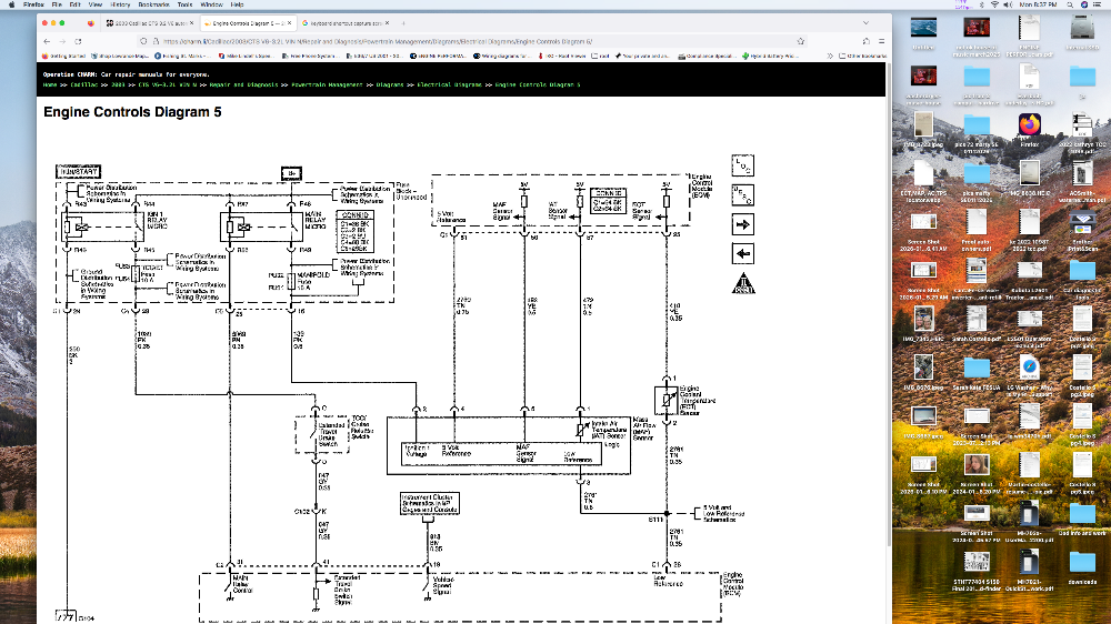
Can you show the PCM connector C1 pinout? I want to trace the low reference lines to C1.
Please Log in or Create an account to join the conversation.
- Tyler
-

- Offline
- Moderator
-
- Full time HACK since 2012
- Posts: 6126
- Thank you received: 1542
Please Log in or Create an account to join the conversation.
- Marti
-
Topic Author
- Offline
- Premium Member
-
- Posts: 137
- Thank you received: 8
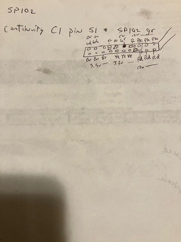
Second, I found on the MAF, Pin 4, tan line is always at 5V, either with MAF plugged in or out. That tan line goes to pin 51 on the PCM which is labeled low reference (measures 5 v at the PCM pin 51). I discovered that it has continuity with a grey line at the splice 102 in the fuse box near the battery. KOEO I measure 5 v at this grey line that somehow has continuity with the MAF pin 4 tan line. See the pic below and the filled in grey line on SP102 is the particular grey line with continuity on the tan line Pin 4 MAF.
Please Log in or Create an account to join the conversation.
- Marti
-
Topic Author
- Offline
- Premium Member
-
- Posts: 137
- Thank you received: 8
Therefore I suspect my main issue is to fix the S111 line that connects the MAF Pin 3, and the ECT and CMP tan low ref lines to the ECM pin 26 (I cut that line to get the engine to start. The incoming line to the ECM which was cut was then grounded to a bolt on the ECM housing) I suspect a bad S111.....
Please Log in or Create an account to join the conversation.
- Marti
-
Topic Author
- Offline
- Premium Member
-
- Posts: 137
- Thank you received: 8
Please Log in or Create an account to join the conversation.
- Marti
-
Topic Author
- Offline
- Premium Member
-
- Posts: 137
- Thank you received: 8
Please Log in or Create an account to join the conversation.
- Marti
-
Topic Author
- Offline
- Premium Member
-
- Posts: 137
- Thank you received: 8
Please Log in or Create an account to join the conversation.
- Marti
-
Topic Author
- Offline
- Premium Member
-
- Posts: 137
- Thank you received: 8
Please Log in or Create an account to join the conversation.
- Marti
-
Topic Author
- Offline
- Premium Member
-
- Posts: 137
- Thank you received: 8

Please Log in or Create an account to join the conversation.
- Noah
-

- Offline
- Moderator
-
- Posts: 5038
- Thank you received: 1119
I don't think this is a frequency generating MAF based on your scope capture and the description of the MAF in shop key as well.
Please Log in or Create an account to join the conversation.
- Marti
-
Topic Author
- Offline
- Premium Member
-
- Posts: 137
- Thank you received: 8
When I ask AI, or chatGPT is says this:
The Mass Air Flow (MAF) sensor in a 2003 Cadillac CTS (3.2L V6) is generally considered a
digital (frequency-based) sensor, which is characteristic of GM vehicles from that era.
Signal Type: While some analog sensors output a variable voltage (typically 0-5V), the 2003 CTS utilizes a hot-wire style sensor that translates airflow into a frequency output (Hz) that is sent to the Powertrain Control Module (PCM).
Testing: Because it operates on frequency rather than voltage, it is best tested using a scan tool to read live data in grams per second (g/s) or an oscilloscope to monitor the frequency.
Physical Type: The 2003 CTS 3.2L uses a hot-wire MAF sensor usually featuring a 5-pin terminal.
Diagnosis Tip: A properly functioning MAF on this engine should typically read roughly 3.0 grams per second at idle (or roughly 1 gram per second for every liter of engine displacemen
Please Log in or Create an account to join the conversation.
- Noah
-
- Offline
- Moderator
-
- Posts: 5038
- Thank you received: 1119
No, but I am sure that this pin out labels pin 4 as 5v reference, but I have been burned by Snap-On & Shop Key before.Are you sure that MAF Pin 4 is not an ECM provided ground or low reference?
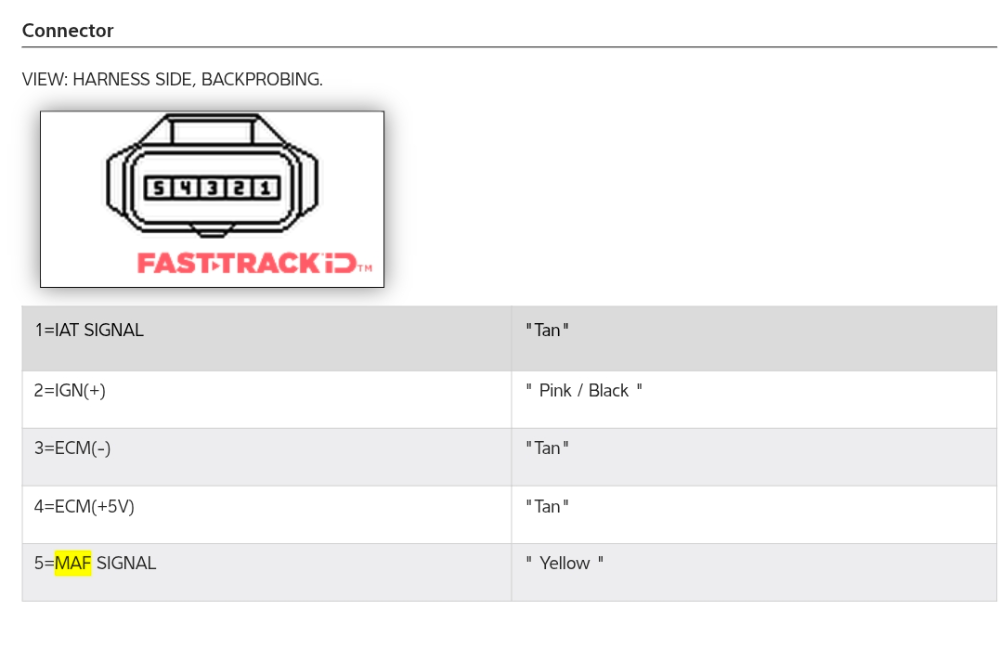
As a matter of fact, if you follow the simplified Mitchell diagram, it shows pin 4 as low ref.
Again, been burned by Snap-On & Shop Key before...
I would say that as long as you only have one pin of the MAF that measures 5v, then that's the 5v reference. If you had multiple pins that measure 5v, then we would have some detective work to do.
There are definitely some discrepancies which understandably complicate the matter.
It may be worth your money to buy a few days worth of service information from AC delco just to know that you are getting accurate service information.
www.acdelcotds.com/subscriptions
Also, be careful with Chat GPT. It's not all that intelligent in my opinion.
I'm not saying the MAF isn't a digital type sensor, general motors certainly use them, but your scope capture isn't a digital signal and shop key doesn't specifically say that it is or is not.
Please Log in or Create an account to join the conversation.
- Marti
-
Topic Author
- Offline
- Premium Member
-
- Posts: 137
- Thank you received: 8
A digital GM Mass Airflow (MAF) sensor uses a 12V supply to heat a sensing element and a 5V reference (or internal circuitry) to monitor temperature, translating air cooling effects into a frequency signal (Hz). As air passes, it cools a hot wire, requiring more current to maintain a constant temperature; the sensor converts this current change into a digital frequency proportional to the mass of airflow.
How the Components Work Together:
12V Power Supply: This provides the necessary power to heat the platinum hot-wire element to a set temperature (often
) above the ambient air temperature.
5V Reference/Signal: In many digital GM systems, the sensor uses a 5V reference to power internal logic circuits that monitor the heat, or it produces a 5V-based pulse-width modulated (PWM) or square-wave frequency signal back to the ECM.
Measurement Process (Hot Wire):
The 12V circuit maintains a constant, high temperature on the wire.
Incoming air cools this wire. The rate of cooling depends on the mass of the air (denser/more air = more cooling).
The sensor increases current to the wire to keep the temperature constant.
Digital Output (Frequency): Instead of a 0-5V analog voltage, the sensor's electronics convert the current required to maintain temperature into a digital frequency signal (measured in Hz).
Low Airflow (Idle): Lower frequency (e.g., lower Hz).
High Airflow (Acceleration): Higher frequency (e.g., higher Hz).
The PCM uses this frequency signal to accurately calculate the mass of air entering the engine for fuel injection, often compensating for air temperature via an integrated IAT sensor.
Please Log in or Create an account to join the conversation.