corolla 2000 TPS sensor signal wire reads 12.volts
- andrameda271
-
 Topic Author
- Offline
- Banned
-

- mercy dropth like a gentle rain
- Posts: 52
- Thank you received: 0
Broke through anti-theft mode got my crank working. again.
re-testing throttle body sensor ref 00 with meter set on volts; signal 12v high; grnd 00 normal; chapter 10 says to jump signal to ground because of the high voltage window range 8 to 12. And low is 1.to 8 volts. Not certain about this fact or fiction.
Afraid to do this without .5000 ohms resister if the 5v reference come back circuit is good. What confusing is that I used ohms to fine ground and avoided the signal wire because of high voltage 12v but place ohm to the remaining wire and got 5v ref. How did this happened?
Is this a shorted sensor that needs replacement? Is this the cause for the fuel pump not priming?
Brake pedal sunk all the way to the floor; is this a brake master cylinder issue with regard to vacuum and air flow and does it affect the idle air control sensor next the throttle sensor?
The car cranks in neutral not in park; got a hodgepodge of symptoms. Let me know your thoughts observation and direction, thank you for your support!
Respectfully,
AG
To be or not to be: do be do be doo!
Please Log in or Create an account to join the conversation.
- Tyler
-

- Offline
- Moderator
-

- Full time HACK since 2012
- Posts: 6124
- Thank you received: 1541
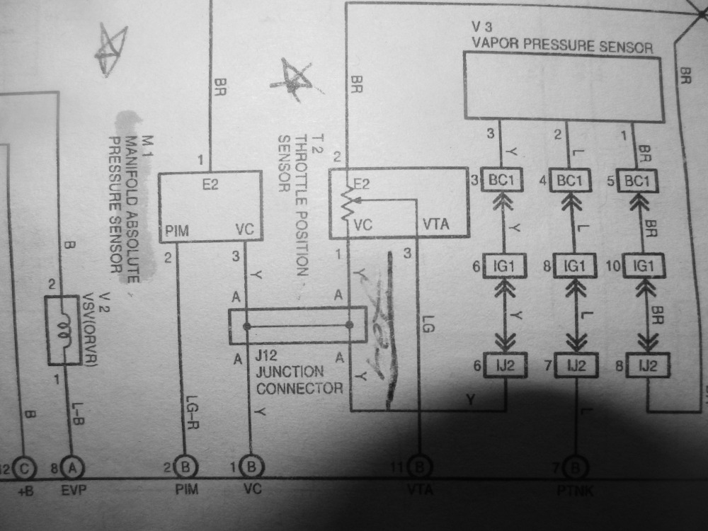
Would you mind clarifying your readings at the TPS for me? Here's the sensor:

Brown is sensor ground, yellow is the 5V reference, and light green is the signal. Please let me know what the voltage reading is on all three wires, KOEO, plugged in and unplugged.
 Obviously, having 12V on any of those is a problem, but we need to be clear about which one is too high.
Afraid to do this without .5000 ohms resister if the 5v reference come back circuit is good.
Good move.
") Until we know where that 12V is coming from, don't worry about shorting anything.
Until we know where that 12V is coming from, don't worry about shorting anything.Is this the cause for the fuel pump not priming?
Probably not, but it might be a symptom of the real problem. Let's follow this issue and see where it takes us.
Brake pedal sunk all the way to the floor; is this a brake master cylinder issue with regard to vacuum and air flow
That's definitely a problem, but not THE problem. With the engine off, the pedal should be rock hard, as there's no vacuum to the brake booster to provide assist. This would indicate a possible mechanical or hydraulic issue with the brake system.
My suggestion is to leave that be for now and get the engine running.
If you happen to get it running during testing, it probably goes without saying that you shouldn't drive it with a brake system issue. Please Log in or Create an account to join the conversation.
- andrameda271
-
Topic Author
- Offline
- Banned
-
- mercy dropth like a gentle rain
- Posts: 52
- Thank you received: 0
Greetings!
Yes on to something really big here!
Will attempt to re-do meter testing on throttle sensor most appreciative!
Respectfully,
Andrameda271
To be or not to be: do be do be doo!
Please Log in or Create an account to join the conversation.
- andrameda271
-
Topic Author
- Offline
- Banned
-
- mercy dropth like a gentle rain
- Posts: 52
- Thank you received: 0
Throttle position sensor has 3 wires, it is a pull down circuit
Looking down from the top of the throttle sensor are 3 colored wires not matching the wire diagrams and 3 different reading, while in neutral only!
Colors are: LG ( 1st wire,light green ref);2nd B-G black w green tracer, mid signal wire; 3rd L-B, blue & black grd to fuel pump:
color configuration n readings:
1- Light green is first wire. reference; reading is 0.01 (0.10 mill volts) what happened to the ref 4v.9mv volts? Unplugged all other sensors, the 5 ref never got pulled up. Is it a defective throttle?
2- Black w green trace, middle wire, reads 12.36v; bat 12.60. voltage drop of 0.034MV
3- Blue/blk wire is grounded to the fuel pump reads 1.67 volts ( one volt + 67 milli volts) high resistance for a ground wire. This should be reading something when it primes, then 00 with key on; these readings received in neutral position of tranny safety switch.
Paul's throttle accelerator test was applied, by back probing wires with sensor connected first, then opening the throttle on all three wires, the throttle stayed at 00, while in park with 00 reading on all three wires in both park and neutral, no throttle acceleration voltage.
Looking for the wiper line in throttle wire diagram connecting to the resister to determine 4v ref, it confused me further; looking at the blue black wire w/ key on reads 1.67v, is this saying that my fuel pump is alive and ready yet I heard no prime sound with key on; perhaps its the crank mode that makes the sound, I did not hear the pump turn. I too afraid to crank it after this 1.67 reading.
The middle wire reads 12.36v this is not normal; its to high for a signal wire, which should read less then, 1volt.
I was afraid to jump the middle wire to ground because of its high voltage; its high resistance 1.67v; could burn the wires to fuel pump?
While in park and the key off the ohm meter read 5volt ref on the light green wire. I was not afraid because Paul points to resistors protecting the ecm;s voltage regulator however the mid signal wire to ground was not jumped; the ecm did not show a back door resistor to regulator through ground.
I did not jump signal wire to the ref wire because I did not have a 5000 ohms resistor and volts extremely high 12v.
In addition, if I really learned the math 1000 milli voltages is equal to 1 amp and the computer can only tolerated 1.2 amps before it burns. I was too afraid to learn by trial and error and ruin a functioning ecm.
It appears nothing seem to help me, wire diagrams; the class room videos nor converting mill volts to volts and to current amps, what i learned by memory is questionable and not precise.
Happy Gatherings and thanks for all your support god bless.
Alex G
To be or not to be: do be do be doo!
Please Log in or Create an account to join the conversation.
- Tyler
-
- Offline
- Moderator
-
- Full time HACK since 2012
- Posts: 6124
- Thank you received: 1541
The IAC on your Corolla gets a 12V feed on the middle wire, a constant ground on another, and a PWM ground from the PCM on the last one. That matches the readings you took. The wire colors don't match, but they didn't match the TPS, either. :silly: If I'm right, then the 1.67V reading you saw would suggest that the PCM is alive and operating the IAC.
To be clear - unless the wiring on your Corolla differs significantly (besides wire colors) from the US model that I can find diagrams for, there is no direct connection between the fuel pump and any of the sensors we're testing.
Maybe try taking measurements at the ECT instead? KOEO, sensor disconnected, measure both pins for voltage. One should read 5V, the other should read zero.
Please Log in or Create an account to join the conversation.
- andrameda271
-
Topic Author
- Offline
- Banned
-
- mercy dropth like a gentle rain
- Posts: 52
- Thank you received: 0
what you call the brn wire as grd is light green reading 0.01 volts on the throttle sensor ; the air control sensor is on the opposite side of the throttle sensor which had the steel cable from accelerator pedal.
What you call yellow wire as the 5v ref on your diagram ; is a black with green trace middle wire which is reading a 12.36 voltage.
the blue with blacj tracer reads 1.67v it seems to be the ground on my wire diagram from haynes corolla repair manuel.
So it is interesting that it is in the reverse order should I risk jumping the 12v wire to ground without a resistor?
I have a 4.7 ohms resistor should I risk jumping the 12 volt wire to the 5v ref wire which reads 1.67?
I have resistors what would be wise?
respectfullly,
Ag
To be or not to be: do be do be doo!
Please Log in or Create an account to join the conversation.
- Tyler
-
- Offline
- Moderator
-
- Full time HACK since 2012
- Posts: 6124
- Thank you received: 1541
andrameda271 wrote: what you call the brn wire as grd is light green reading 0.01 volts on the throttle sensor ; the air control sensor is on the opposite side of the throttle sensor which had the steel cable from accelerator pedal.
OK cool, thanks for clarifying!
No insult meant! Just making sure we're on the same page.What you call yellow wire as the 5v ref on your diagram ; is a black with green trace middle wire which is reading a 12.36 voltage.
the blue with blacj tracer reads 1.67v it seems to be the ground on my wire diagram from haynes corolla repair manuel.
Silly Toyota, why make the wire colors different?
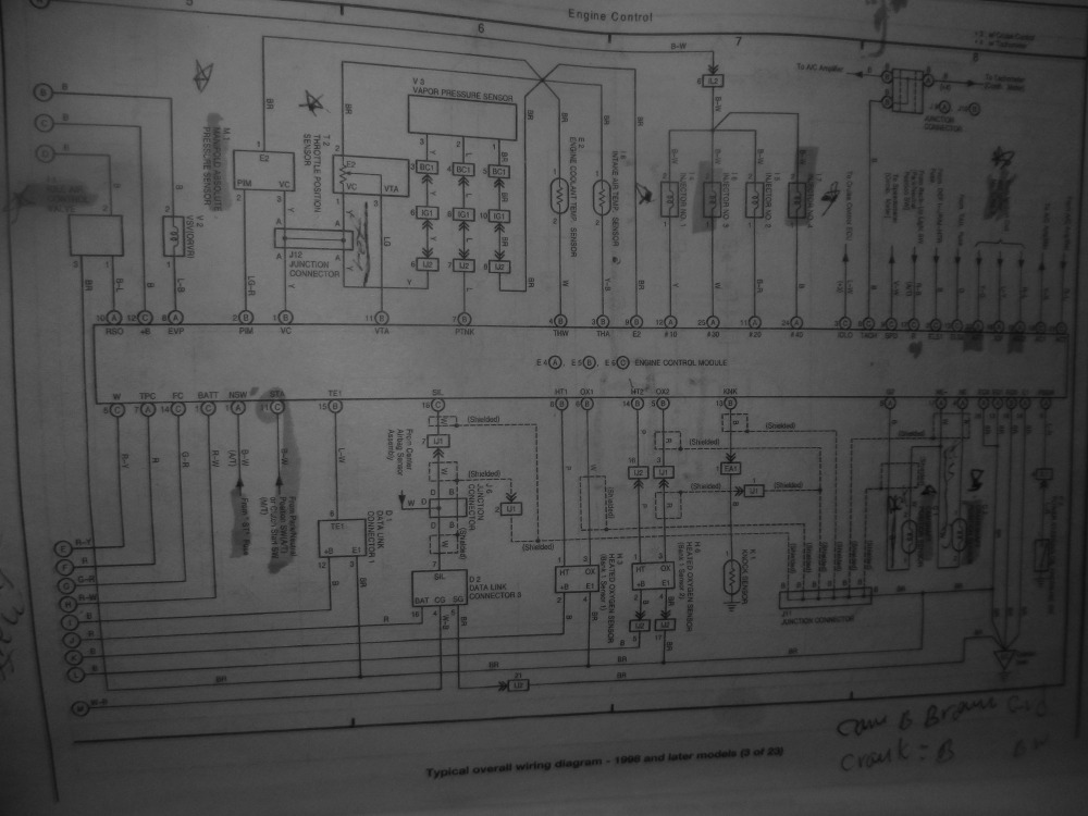
 :lol: Is there any way you could take a photo of the Haynes diagram and post it here? That's help me tremendously.
So it is interesting that it is in the reverse order should I risk jumping the 12v wire to ground without a resistor?
I have a 4.7 ohms resistor should I risk jumping the 12 volt wire to the 5v ref wire which reads 1.67?
Negative, let's not jump anything until we know what's what. Mostly, I'm worried that if you add a ground to either circuit, you'll be providing a ground path for other high current devices that are also looking for a ground, and end up cooking something.
Do me a favor and check the ECT as I described above? If you see the same 12V or the 1.67V reading that you saw on the TPS, we're onto something.
Please Log in or Create an account to join the conversation.
- andrameda271
-
Topic Author
- Offline
- Banned
-
- mercy dropth like a gentle rain
- Posts: 52
- Thank you received: 0
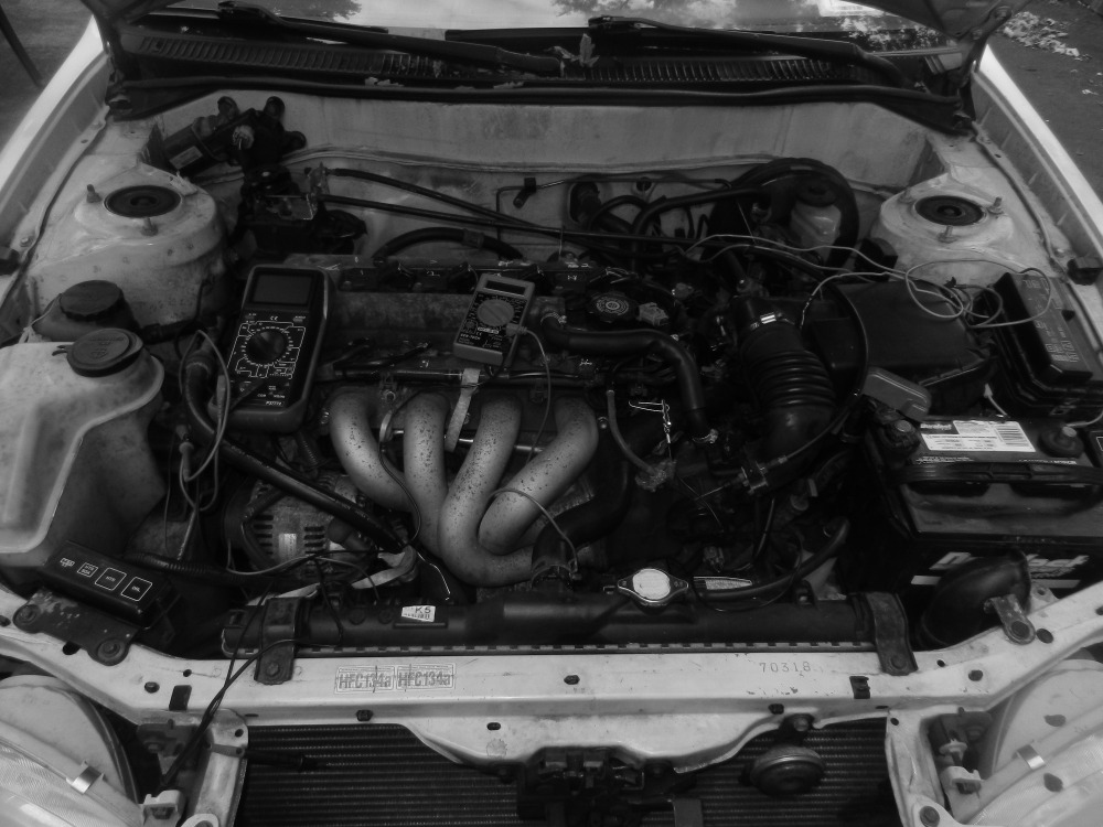
OK will take pix of throttle and intake air controller;
compare the meter readings; then the Haynes wire diagram I have colored.
this website may only allow 1 or 2 picture.
Thank you for wise observation allowing a jump opens a ground path, for something else thats shorted.
Respectfully
AG
To be or not to be: do be do be doo!
Please Log in or Create an account to join the conversation.
- andrameda271
-
Topic Author
- Offline
- Banned
-
- mercy dropth like a gentle rain
- Posts: 52
- Thank you received: 0

To be or not to be: do be do be doo!
Please Log in or Create an account to join the conversation.
- andrameda271
-
Topic Author
- Offline
- Banned
-
- mercy dropth like a gentle rain
- Posts: 52
- Thank you received: 0
in this car the colors of wires are different. light green is ground 0.01v; dark middle wire with green trace reads 12. 36v; blue/ black wire reads 1.67v, which according to your sensibilities is the ref 5.
To be or not to be: do be do be doo!
Please Log in or Create an account to join the conversation.
- andrameda271
-
Topic Author
- Offline
- Banned
-
- mercy dropth like a gentle rain
- Posts: 52
- Thank you received: 0
Hello Tyler and noah,
Sent you some photos: scroll down to look at them-1 Haynes wire diagrams of throttle sensor and fuel pump ground and a description of wire colors with voltage readings? p;ease let me know to confirm my next step and direction, thanks for support.
Alex
To be or not to be: do be do be doo!
Please Log in or Create an account to join the conversation.
- andrameda271
-
Topic Author
- Offline
- Banned
-
- mercy dropth like a gentle rain
- Posts: 52
- Thank you received: 0
Scroll downward to see the pictures of Haynes wire diagram on throttle sensor and engine bay location; and colores that do not match.
Respectfully,
AG
To be or not to be: do be do be doo!
Please Log in or Create an account to join the conversation.