1995 Jeep Grand Cherokee 4.0L
- graywave
-

- Offline
- Elite Member
-

- Adv. Diagnostics New Hampshire
- Posts: 303
- Thank you received: 80
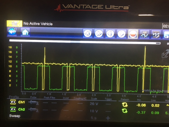
One thing I notice with your setup is channel one (yellow) is set to "Test Lead" and not "Ignition Probe". It works better even when scoping on the primary circuit to set the scope in ignition probe mode for which ever channel is probing coil control. Change that and take another snap shot of coil control. Even if there is no spark from the tower we should still see activity on that coil.
Do you have an amp probe? It would be good to take a current measurement of that coil to see if its shorted either on primary or secondary.
Also I learned that the crank sensor goes to 5v with the windows so if you ever have the crank sensor not spike to 5v on these I would highly suspect a sensor problem instead of something mechanical. If it stays at 5v for too long or turned on to early to 5v, something mechanical like spacing would be a suspect.
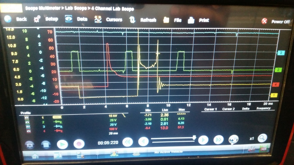
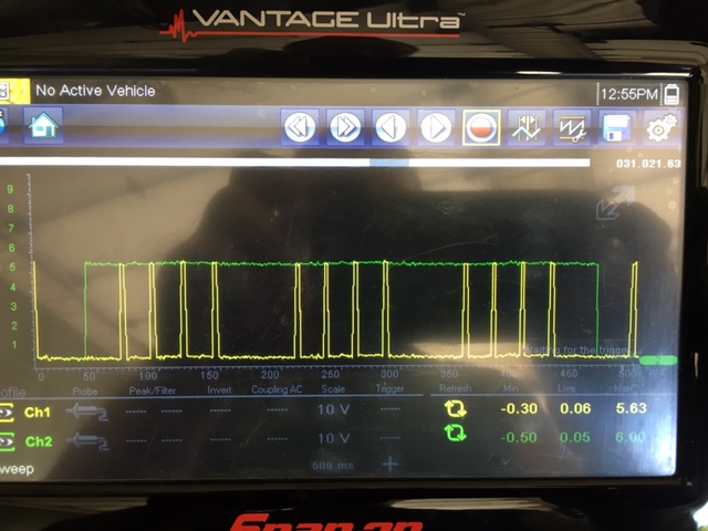
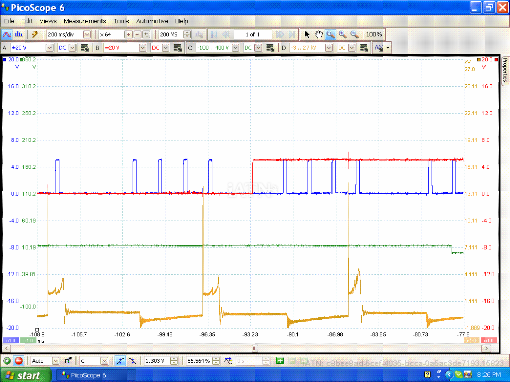
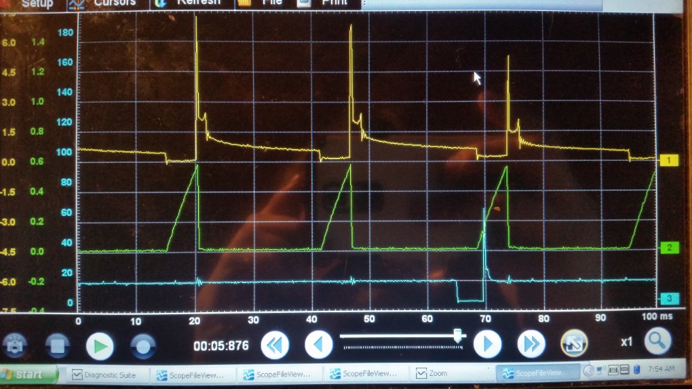
Here are a couple shots. The crank sensor is a problem with this one so that large 5v turn on in the green channel at the beginning and end of the cam signal is bad so ignore that. This vehicle does run fairly smooth just hicups now and then.
Yellow: IGN COIL CONTROL AT PCM
Green: CKP SENSOR AT PCM
Blue: CMP SENSOR AT PCM
Red: Cyl #1 Fuel Injector Control Wire at Fuel Injector
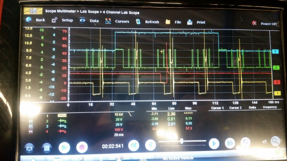
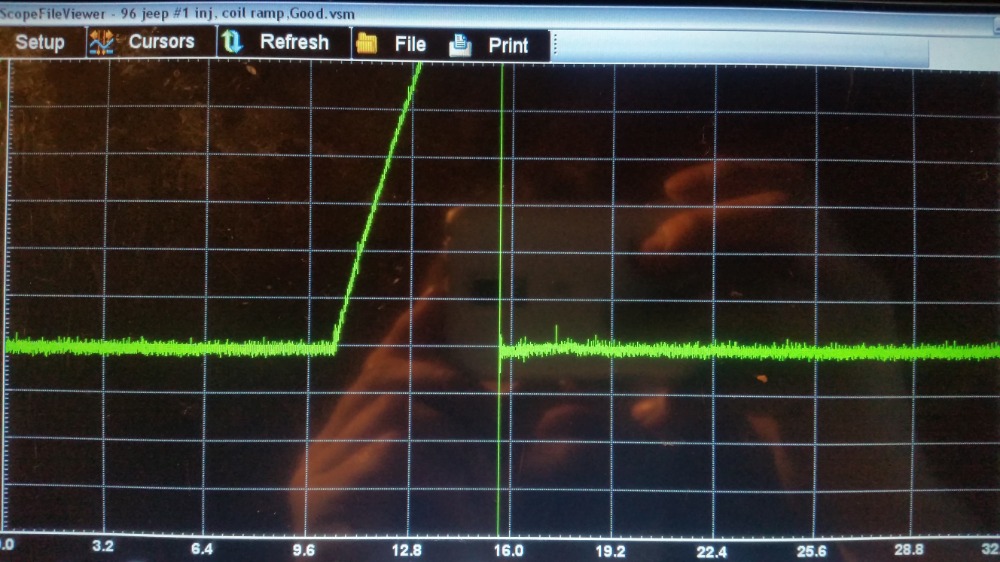
Here is what good coil control looks like on a 96 Jeep 4.0
Here is a Shot viewed out with crank and cam, #1 Inj to sequence the #1 cyl ignition event.
Confirm what it's not, and fix what it is!
Please Log in or Create an account to join the conversation.
- graywave
-
- Offline
- Elite Member
-
- Adv. Diagnostics New Hampshire
- Posts: 303
- Thank you received: 80
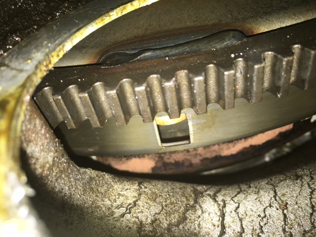
Your flywheel and distributor look to be correct for your year. They also look like they are timed correctly.
Just so we can see everything in detail which will also tell us if something is not timing right...
CKP Sensor, CMP Sensor, #1 injector and Ignition Coil Ground Control.
1. Set your scope so the channel scoping the ignition coil is set to "Ignition Probe" and you may need to put the KV scale is high as it will go. Attenuators work good for keep ign signals under control on the scope.
2. CKP & CMP sensor channels you can set to 20v scale.
3. The fuel injector channel you will probably need to set it to 400v scale. Attenuators help with this too.
Set your time base to 50ms. Have someone crank the engine and fill the buffer and hit the stop button then save all frames. Now you can adjust zoom levels and other parameters. You can take screen shots with your phone and if you have an online drive (cloud drive) like google drive, you can upload the entire scope file. May need to use a usb drive to transfer file to another pc.
I would be interested to see what everything looks like.
Matts Auto wrote: Ok, so i removed the starter to inspect reluctor ring & found what i think was part of a sticker stuck in one of the holes. I removed it with a pick, reinstalled starter & no change. So i replaced crank sensor with a new aftermarket ( i know aftermarket isn't always a good choice) & no change. I tried adjusting crank sensor but really can't get much movement out of a one bolt sensor. Customer has no history on this vehicle as he picked it up not running. The flexplate looks new so i don't know if there's a possibilty of wrong flex plate installed.
Confirm what it's not, and fix what it is!
Please Log in or Create an account to join the conversation.
- Matts Auto
-
 Topic Author
- Offline
- Premium Member
-

- Posts: 155
- Thank you received: 28
Please Log in or Create an account to join the conversation.
- graywave
-
- Offline
- Elite Member
-
- Adv. Diagnostics New Hampshire
- Posts: 303
- Thank you received: 80
Here are the shots you should grab with a 2ch
1.CMP and CKP at 50-100ms time base. 100ms is probably fine for cranking
2. CKP and #1 Fuel Injector (Injector Timing and Control Confirmation)
3. CKP and Ignition Coil Ground Control (Set the probe type to Ignition Probe) (Ign Timing and Control Confirmation)
This will tell us how everything is timing up and the condition of everything and how the coil is doing internally and if the PCM is trying to give proper control.
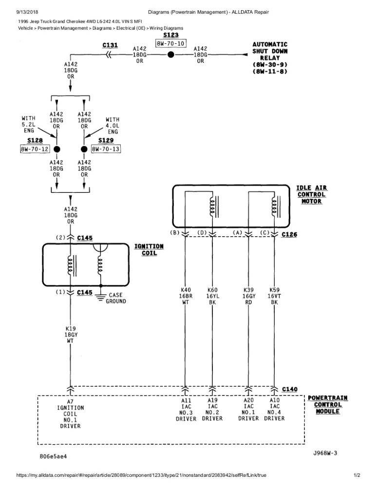
The ignition coil needs to have a good ground I believe through its housing to the engine. A diagram shows it grounded that way.
Confirm what it's not, and fix what it is!
Please Log in or Create an account to join the conversation.
- Matts Auto
-
Topic Author
- Offline
- Premium Member
-
- Posts: 155
- Thank you received: 28
Please Log in or Create an account to join the conversation.
- graywave
-
- Offline
- Elite Member
-
- Adv. Diagnostics New Hampshire
- Posts: 303
- Thank you received: 80
I know you have a no spark situation but just some food for thought in case you haven't thought of it...You can also use an incandescent test light to check spark. clamp end to ground and probe end to coil. I think its better actually cause you can see just how far the spark will jump and this will determine how much energy that coil is capable of producing. I find most coils will jump 3/4-1" just fine. If its down around 1/2" thats usually ok but might be showing signs of weakening, should still start and run just fine. Less than that and I could call a bad coil.
Confirm what it's not, and fix what it is!
Please Log in or Create an account to join the conversation.
- graywave
-
- Offline
- Elite Member
-
- Adv. Diagnostics New Hampshire
- Posts: 303
- Thank you received: 80
I would say just grab CKP & Ignition and then CKP and #1 Fuel Injector. In fact CMP & #1 Injector would also help to judge timing of everything since there are no major sync notches in the CKP signal that can allow us to notice 720 degrees of crankshaft rotation. I can then compare them all and judge timing.
I do believe, if you have injector control, then you should have coil control. If you have good coil control, then just to make sure its housing is grounded and you have good power to the coil which I believe you already tested.
Whats interesting is the 96 Jeep I work on only uses a 5v REF to the sensors, not 8v.
Confirm what it's not, and fix what it is!
Please Log in or Create an account to join the conversation.
- Matts Auto
-
Topic Author
- Offline
- Premium Member
-
- Posts: 155
- Thank you received: 28
Please Log in or Create an account to join the conversation.
- graywave
-
- Offline
- Elite Member
-
- Adv. Diagnostics New Hampshire
- Posts: 303
- Thank you received: 80
When you scope ignition control circuits on 2 wire ignition coils, sometimes its better to go right down to 20-50ms to get a full detail of the ignition waveform. Give it a shot, play around. you can send pictures of 20,50,100 and I can let you know which ones I prefer for analyzing detail just as a reference for your scoping future. The actual "numbers" for time base and voltage scales I don't put to much thought into, its more of just wanting the right settings to get the detail or repetition you need to make a call. I do have a generic time base range which I normally go to and that is 20-50ms usually for ignition and 100-200ms for mostly everything else.
It varies from vehicle to vehicle especially when you start scoping variable reluctance sensors producing AC sine waves.
If you ever use another scope other than a snap on scope, you might get mixed up with time bases and voltage scales because most other scopes set everything "Per Division" instead of "Per Screen" like snap on does it. So depending on how many divisions (squares) are across the screen will judge your "screen" time base or voltage scales. So if there are 5 divisions horizontally across the screen and you want the same 100ms screen, you would need to set other scopes to 20ms/div. Same goes for vertical scales. Little food for thought.
Confirm what it's not, and fix what it is!
Please Log in or Create an account to join the conversation.
- Matts Auto
-
Topic Author
- Offline
- Premium Member
-
- Posts: 155
- Thank you received: 28

Please Log in or Create an account to join the conversation.
- Matts Auto
-
Topic Author
- Offline
- Premium Member
-
- Posts: 155
- Thank you received: 28
Please Log in or Create an account to join the conversation.
- Matts Auto
-
Topic Author
- Offline
- Premium Member
-
- Posts: 155
- Thank you received: 28
Please Log in or Create an account to join the conversation.
- graywave
-
- Offline
- Elite Member
-
- Adv. Diagnostics New Hampshire
- Posts: 303
- Thank you received: 80
Grab some cmp / Ign ctrl * ckp / Ign ctrl shots. We need to figure out why your coil is not firing. You should see control to your coil if you have control to your injectors. Compare control at PCM and at IGN COIL. Make sure IGN CTRL is making its way to that coil.
Do you have a low AMP Probe that measures on a scale of 1mv/10ma (20a) or 1mv/100ma (40a)? 40amp could also be 10mv/1A scale, same thing. A current ramp test could tell us if the primary or secondary winding is shorted.
Honestly If you have good control and good power to the coil and the body is grounded well, that coil should fire.
Below I highlighted the area you need to change. You should be able to tap on the probe to change it. You might need to be "recording" aka "Scope Live" to make the change. Then set your voltage/KV scale as high as you can go. I believe it will probably go off the screen a bit "if" the coil was actually firing. Make sure coil is attached to the distributor like normal.
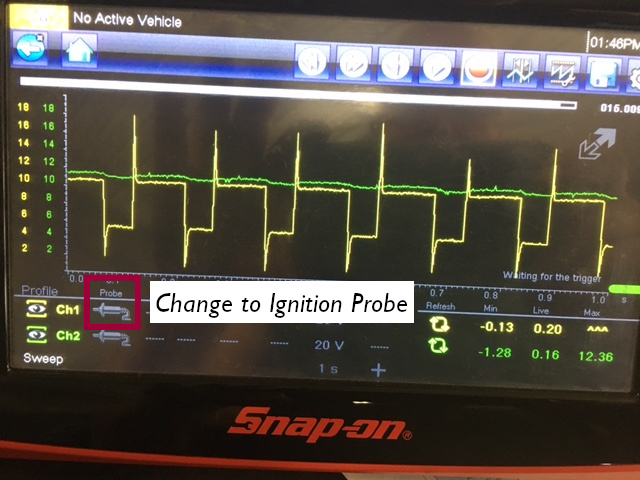
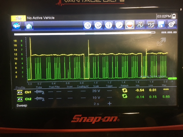
Here is a known good from a 1995 Jeep 4.0. Wiring diagrams do show 8v REF voltage to sensors but that might only be to run the hall sensing circuit. Probably just a 5v supply on the signal wire.
Confirm what it's not, and fix what it is!
Please Log in or Create an account to join the conversation.
- Matts Auto
-
Topic Author
- Offline
- Premium Member
-
- Posts: 155
- Thank you received: 28
Please Log in or Create an account to join the conversation.
- chief eaglebear
-
- Offline
- Platinum Member
-

- Posts: 340
- Thank you received: 70
Please Log in or Create an account to join the conversation.
- graywave
-
- Offline
- Elite Member
-
- Adv. Diagnostics New Hampshire
- Posts: 303
- Thank you received: 80
What chief eaglebear and I are trying to explain is the body ground on the coil is very important as well as computer case and computer grounds
Here is a diagram of the ignition circuit. Notice the "case" ground on the 2ndary coil winding.
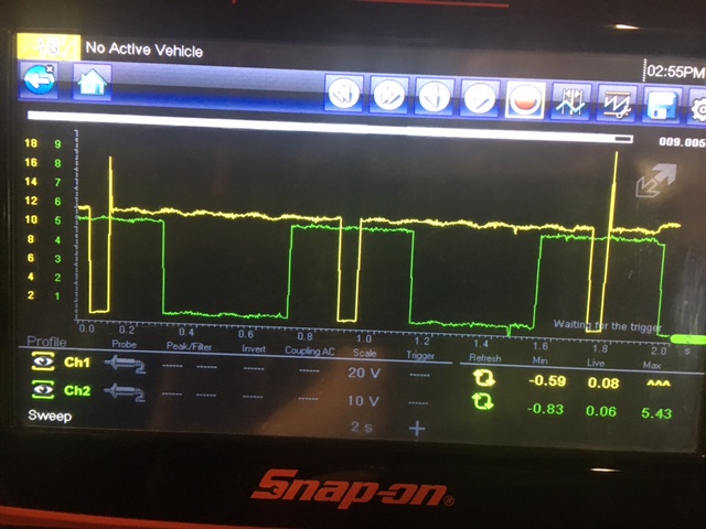
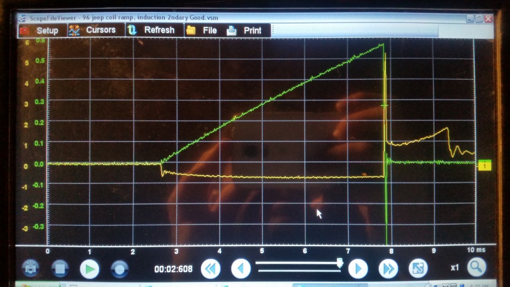
Notice this capture of mine. Control Side Ground is pulled almost all the way to ground. Measurements vary between 200mv to 1.4v on the ground side on the coil I tested while the coil charges up. I would like to see it go all the way to ground but there might be current limiting going on maybe....not sure.

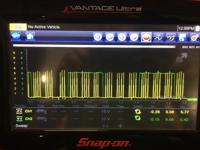
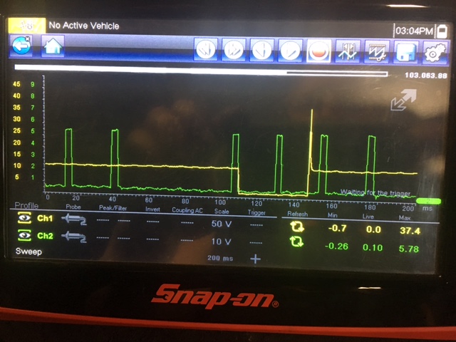
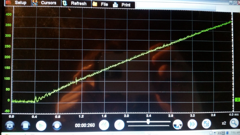
Here is a snap shot of #1 Inj, Coil 2ndary with Inductive Pickup and Coil Current Ramp
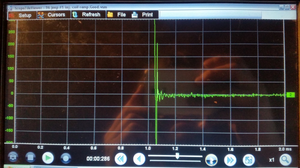
Ign Coil primary winding current ramp showing secondary winding oscillations at beginning.
I do believe these oscillations at the very end of the current ramp are also secondary winding oscillations or possibly a mix of both primary and secondary?
Another shop of coil current ramp with Ign secondary with inductive pickup
Confirm what it's not, and fix what it is!
Please Log in or Create an account to join the conversation.
- graywave
-
- Offline
- Elite Member
-
- Adv. Diagnostics New Hampshire
- Posts: 303
- Thank you received: 80
Confirm what it's not, and fix what it is!
Please Log in or Create an account to join the conversation.
- Matts Auto
-
Topic Author
- Offline
- Premium Member
-
- Posts: 155
- Thank you received: 28
Please Log in or Create an account to join the conversation.
- graywave
-
- Offline
- Elite Member
-
- Adv. Diagnostics New Hampshire
- Posts: 303
- Thank you received: 80
The issue was probably the driver not pulling the control side all the way to ground or the pcm didnt have a good ground internally. Thats what it was looking like in your first capture but wanted to see the ign probe waveform to make a call.
On your first capture, you can see when the voltage gets pulled down, its only pulled to about 4v, 2v max.
In this situation, the ignition coil would not be charging up to capacity and would not create a big enough electro magnetic field to induce high voltage needed to jump a gap any. Its possible i suppose that the original coil shorted out and took out the driver.
I would invest in a low amp 20a/40a combo amp clamp. This could probably give you the answer right away.
Way to stick with it!
Confirm what it's not, and fix what it is!
Please Log in or Create an account to join the conversation.
- Matts Auto
-
Topic Author
- Offline
- Premium Member
-
- Posts: 155
- Thank you received: 28
Please Log in or Create an account to join the conversation.