2017 CTS V Canbus delete
- TexasGrench
-
 Topic Author
- Offline
- New Member
-

- Posts: 7
- Thank you received: 0
So kindly assist me with completing my journey of identifying the fix, bypassing component(s) on the Canbus, or deleting the Canbus altogether so I can use the 2017 harness.
I am only able to get a Launch Scanner to communicate with the AC/Heating module and Keyless Entry Module after manually entering the VIN. No scanner will communicate with the ECM nor see any other module mentioned within all the fixings. I purchased a 2017 LT4 engine & trans (sitting on a crate in my garage), with pretty much all the fixings. ECM (security deleted), TCM, BCM, Brake pedal, Accelerator pedal, 2 Remote receiver modules, all 3 fuse boxes, 1 Key fob, Floor shifter, Odometer, Start Button, MAF Sensor, AC/Heating module, wiring harness w/ power cable to rear battery connections (all from original CTS V). The harness was "cut out" of a donor vehicle so it is missing internal door and interior seats, seatbelt connectors etc. I have purchased another key fob, Keyless Entry module, Immobilizer, Electronic Brake Control Module, Fuel Pump Control Module, Shift indicator, and possibly 1-2 other things I can't recall.
I have managed to connect it all and everything appears to work when I push the Start button down to having to place the keyfob with the Immobilizer before it will enable the start button. I can push the Start button and It enters accessory mode. The Gauge cluster lights up, displays everything that it does not see as well as tells me that I need to press the brake to start the engine. I have to press the brake before it will initiate the start protocols and crank/run relay engages and I can also manually engage the starter relay and the engine with crank over. I even can turn the engine off via the Start button and the accessory interior lights will even light up.
I have tracked down all of the twisted Blue/While Canbus high/low lines to their modules. I have continuity-checked them from the ECM back to each device and junction and have managed to go from infinity reading on PINs 6 and 14 to now reading 120 ohms. One at a time I have disconnected the TCM, Electronic steering motor, and EBCM, and got an infinity reading per disconnected module. I can disconnect in the same fashion; the Fuel Module, Stability Control module, and BCM and the resistance remains 120ish ohms. I keep the battery charged above 12v.
Kindly respond with a positive direction on achieving the goal of being able to communicate with the ECM. ScannerDanner FORUM to the rescuuuUE!
JStyl
Please Log in or Create an account to join the conversation.
- Chad
-

- Offline
- Moderator
-

- I am not a parts changer.
- Posts: 2129
- Thank you received: 715
"Knowledge is a weapon. Arm yourself, well, before going to do battle."
"Understanding a question is half an answer."
I have learned more by being wrong, than I have by being right.
")
Please Log in or Create an account to join the conversation.
- Noah
-

- Offline
- Moderator
-
- Give code definitions with numbers!
- Posts: 4959
- Thank you received: 1111
I was wondering the same. Either way, looks like the network is open, or missing a module with one of the terminating resistors.Into what YMM are you installing this 2017 setup?
"Ground cannot be checked with a 10mm socket"
Please Log in or Create an account to join the conversation.
- TexasGrench
-
Topic Author
- Offline
- New Member
-
- Posts: 7
- Thank you received: 0
I did a continuity check on both PIN 6 /14 to ground and PIN 6 screamed like a little girl's first needle poke from a Doctor. I traced that down to a 6 PIN connector (dual twisted Blue/While( high/low canbus) that stepped down to essentially (2) 2 wires (changed colors) connectors and split. Purple White (under hood fuse block), Red White (trunk fuse block), Both Blue (high) changed to Blue/Purple and split to Passenger side 2 PIN connecter and Drivers side with a ground. The scream came from the passenger side 2 PIN only that I isolated to the interior/rear harness that contains the BCM, Gauge cluster, etc. I disconnected all devices and disconnected the PassSide from GRN and screaming stopped. I disconnected the 2 PIN from 6 PIN and only the 1 Blue(high) screamed. I checked the DrvSide 2 PIN both before and after disconnecting from the 6 PIN and no issues. While PassSide Blue(high) was screaming, I twisted/wiggled/unwrapped and was only able to find the short to what purposely connected wire junction/loop of crimped (4) Blues and (4) Whites. Inquiring mind that want to know, YES I cut the junction and the little girl stopped screaming. I obviously did the DIY thing and connected the highs and low in multiple combinations and finally got like 2.5v to low 3ish volts and 1.7v to mid 2ish volt on the low side. Infinite ohms and still no communication to ECM. Now that I think about it, I did remove all relays from the interior fuse block but did not disconnect power from the interior fuse block. I did remove power from UHB and Trunk FB.
JStyl
Please Log in or Create an account to join the conversation.
- Chad
-
- Offline
- Moderator
-
- I am not a parts changer.
- Posts: 2129
- Thank you received: 715
Total network resistance should be 60 Ω....two 120 Ω resistor, in parallel.
> 120 Ω + 120 Ω = 60 Ω (One resistor at each end of the network)
As Noah pointed out, you are missing a terminating resistor. The schematics are for multiple option packages. You must decipher the schematic to match what you have. For example:
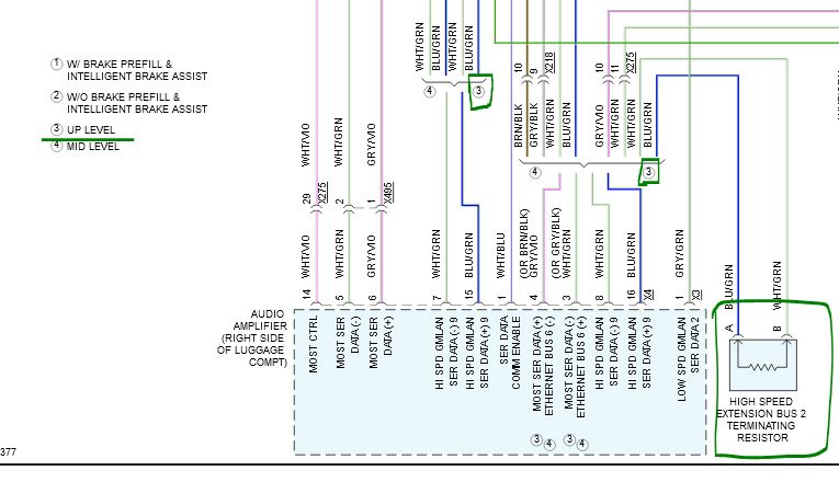
Here, a "3" corresponds to the "up level" package, and one of the terminating resistors is an external resistor.
"Knowledge is a weapon. Arm yourself, well, before going to do battle."
"Understanding a question is half an answer."
I have learned more by being wrong, than I have by being right.
Please Log in or Create an account to join the conversation.
- Chad
-
- Offline
- Moderator
-
- I am not a parts changer.
- Posts: 2129
- Thank you received: 715


"Knowledge is a weapon. Arm yourself, well, before going to do battle."
"Understanding a question is half an answer."
I have learned more by being wrong, than I have by being right.
Please Log in or Create an account to join the conversation.
- TexasGrench
-
Topic Author
- Offline
- New Member
-
- Posts: 7
- Thank you received: 0
Great to know that the resistor is external, which means it was mostly cut out of the circuit and also means I can get one and add it back.
I will locate the circuit that appears to be near the Harmon Kardon/Onstar device and report back after 4 pm CST.
JStyl
Please Log in or Create an account to join the conversation.
- TexasGrench
-
Topic Author
- Offline
- New Member
-
- Posts: 7
- Thank you received: 0
I wasn't sure where the other terminating resistor was located and now that I cut the pre-crimped High/Low loop it went back to infinity but able to see voltage on both High/Low with no resistance. Curious why it is short to group when that junction is crimped. I did disconnect the Harmon/Onstar module but still was getting a short to ground. I am afraid even after adding the second external 120ohm resistor there still will be that short to ground if I reconnect that junction how it was.
JStyl
Please Log in or Create an account to join the conversation.
- TexasGrench
-
Topic Author
- Offline
- New Member
-
- Posts: 7
- Thank you received: 0
This time when I scanned the system after troubleshooting I was able to see three more modules. The gauge cluster, audio amp, performance data module, along w/ keyless entry module and ac/heating.
Troubleshooting: I was not able to locate the external resistor BUT, I was able to read 120 ohm on both sides of the X275 connector and at the X276 connector. With three BLU (high) connected at the crimped junction that I cut, I read 120 ohms at the junction, 125 ohms across the OBD2/DL, and 2.5 high/1.5 low across at OBD2/DL. Once I connect the fourth BLU at the junctions the short returns. I traced that BLU wire to the shifter indicator module, so I will start there tomorrow.
Also, I do not have the Windshield camera or the Human Interface module. If either of those are preventing communication to the ECM is there a way to bypass them, like connecting them in a loop, so to speak?
JStyl
Please Log in or Create an account to join the conversation.
- Chad
-
- Offline
- Moderator
-
- I am not a parts changer.
- Posts: 2129
- Thank you received: 715
I do not have the Windshield camera or the Human Interface module. If either of those are preventing communication to the ECM is there a way to bypass them
Disconnect them, and jumper the CAN bus back together, at the connector.
"Knowledge is a weapon. Arm yourself, well, before going to do battle."
"Understanding a question is half an answer."
I have learned more by being wrong, than I have by being right.
Please Log in or Create an account to join the conversation.
- TexasGrench
-
Topic Author
- Offline
- New Member
-
- Posts: 7
- Thank you received: 0
HOW do I troubleshoot the data lines?
On the engine side of the harness, I've located 4 sets of data lines. 2 blue/white and 2 blue-yellow/white that connect to the electrical steering motor that I wanted to loop. Lets call them Top Twisted and Bottom Twisted. With the battery connected only the Top white reads 1-1.4v. In accessory mode, only the Top white reads 1-1.7v. When in On/Drive mode (green) start button, the Top and Bottom white reads 1.4-1.9v and only the Blue bottom reads .7-1.5v. If I have the top blue (loop/connected ) to the bottom blue only. The start button no longer works and the same happens with the top white and bottom white are connected (looped). I am hoping someone can explain what this means and how to troubleshoot it.
I disconnected the TCM and there is only voltage present on the data lines once both top and bottom data lines are connected at the steering motor connector.
Thanks
JStyl
Please Log in or Create an account to join the conversation.