Re:Re:Re:Re:Re:Re:Re:37 year old coil works, new OEM MOPAR won’t
- simclardy
-

- Offline
- Senior Member
-

- Posts: 78
- Thank you received: 7
Again. I don't know how your vehicle works, but we need to find out. I would ask these 3 questions to start. 1) do I have proper power and grounds at the computer and the essential systems needed to start the vehicle. 2) am I getting a good TDC (top dead center) signal to the computer? I assume the CPS is all it needs, but maybe a camshaft position sensor as well? 3) is the computer properly controlling essential systems?
So as far as I can tell, you are not getting a good control signal to your coil. You might do the test light test at the computer. To rule out damaged wire. (Careful probing your computer)
But my next step is to get a schematic and start testing power and grounds.
Hope this helps.
Sent from my SM-G970U using Tapatalk
Please Log in or Create an account to join the conversation.
- ferris48
-

- Offline
- Premium Member
-

- Posts: 129
- Thank you received: 47
I looked at '97, '98, and '99 diagrams and I cannot find this splice. 25c, or C25 on the diagram, goes solely to the alternator.I have a chart that I made when testing continuity as well as one showing the pins on each of the PCM connectors. The grey wire goes to pin #7a (the black PCM connector) and the Dark Green/Orange wire goes to pin #25c it is labeled “Generator Driver” when I tested continuity this is the wire that lite up from coil Dark Green/Orange wire. I understand the Dark Green/Orange wire is spliced with the ASD.
You have more voltage on your ground lead than your other lead so the voltage displayed is negative. I use a plain old multimeter and if you place the black lead to battery positive and the red lead to negative, you'll get negative voltage.What is with the minus .07 volt reading? That confuses me, I can understand .0 volts not a minus .07 is this significant?
Please Log in or Create an account to join the conversation.
- mmorris923
-
Topic Author
- Offline
- Junior Member
-

- Posts: 35
- Thank you received: 1
I know based on the tests that I have good coils within spec on primary and secondary resistances..To anybody reading this thread if you have any ideas or suggestion please comment. Your idea/suggestion might lead to the understanding that solves this problem.
Please Log in or Create an account to join the conversation.
- ferris48
-
- Offline
- Premium Member
-
- Posts: 129
- Thank you received: 47

Please Log in or Create an account to join the conversation.
- simclardy
-
- Offline
- Senior Member
-
- Posts: 78
- Thank you received: 7
Your battery negative should have a low resistance path to frame of your car and any point that is "ground".
The other test I love is your non led probe because this will load the circuit. Keep in mind you can damage your pcm by overloading certain circuits.
Definitely follow up with ferris on his schematic questions.
Cheers
Sent from my SM-G970U using Tapatalk

Please Log in or Create an account to join the conversation.
- mmorris923
-
Topic Author
- Offline
- Junior Member
-
- Posts: 35
- Thank you received: 1
Point of clarification: Fuse 10 in my Junction Block (fuse panel in passenger compartment) is: (15A) back-up lamp switch, transmission etc.”
Fuse 11 “(20A) PCM, transmission control module etc”
Fuse 10 in the PDC is a “20 Amp Yellow-Auto Shutdown Engine Controller; Fuse 11 is ASD O2 Sensor”
This is from my operator’s manual that is original to the Jeep and matches the actual fuse blocks respectively. I wonder if the fact that my build date is June of 1997 may account for the difference. Your observation is not the first difference as wire color issue popped up on the Cherokee Forum. I understand that Jeep is well known for confusing part numbers and changes during the model year—that’s what I’ve been told. I’ve been challenged on pin #s in the PCM connectors and even the shape of the pins in the coil. I guess that what can make this process additionally difficult.
I am going to check the factory service manual to verify which pin for the ASD is the ground. I thought C2 was the power to the coil but I’ll re-verify that as well. I do have a digital copy of the Factory Service Manual which vaguely recall shows the relay pins in the connector section. I’m not real good at following a wiring diagram but I can kind of follow something’s. I’ve pulled the Air-Box and have the PCM connectors opened up to back-probe to check voltages, etc.
Simclardy’s comment about damaging the PCM by overloading certain circuits is what makes very cautious in trying to a test I’m not sure of the instructions. I am not a fearful person but that does scare me. Thanks for working with me…
Please Log in or Create an account to join the conversation.
- mmorris923
-
Topic Author
- Offline
- Junior Member
-
- Posts: 35
- Thank you received: 1
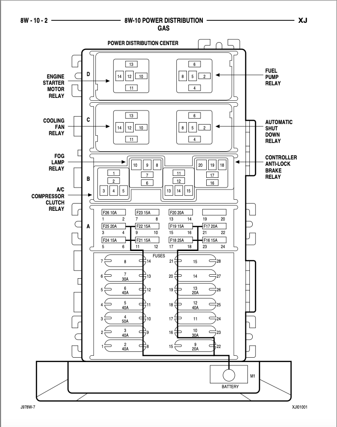
Attached is:Power Distribution 8W-10-2 & fuel Ignition System 8W-30-5 from the Factory Service Manual.
I measured the ASD voltage using a wire in the cavity with the relay replaced: Cavity 2 Fused B(+) measured 12.37 volts with the key off and 12.26 volts with the key on.
Cavity 4, Fused Ignition measured 0.0 volts key off and 12.11 volts key on.
I haven’t measured Cavity 8, Automatic Shut Down Relay Output yet—will do that next.
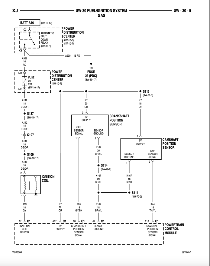
I believe in studying the No Start Tests charts along with Fuel Ignition System 8W—30-5 that first step is to back-probe the DG/OR wire at the coil connector and measure voltage with key on and key off—is that correct? This may be elementary to some of you following this thread, to me this Brain Surgery, I really don’t want to kill the patient!
Probably unrelated, yesterday I measured the following, the battery measured 12.27 volts at the start with my digital volt meter.
I measured all the 5-volt references back-probing all the sensors at both the PCM and the sensor connectors with the key on (I removed the key each time I pulled the PCM connectors to back-probe the wires—then turned key on to measure voltage).. They all measured 5.11-5.13 except for the Throttle Postion Sensor it measured 4.67 volts at both the PCM and the TPS connector. I also measured the 5 Volt supply-31B at 5.14 volts; Fused Batter-22A at 12.23 volts, Fused Igntion Switch (run/start) measured 12.01 volts.
Please Log in or Create an account to join the conversation.
- mmorris923
-
Topic Author
- Offline
- Junior Member
-
- Posts: 35
- Thank you received: 1
This is from the Cherokee Forum, I wanted to keep this Forum alive with what is going. It seems from the Cherokee comments that this may be the problem area. I am cautiously optimistic until the solution is found …
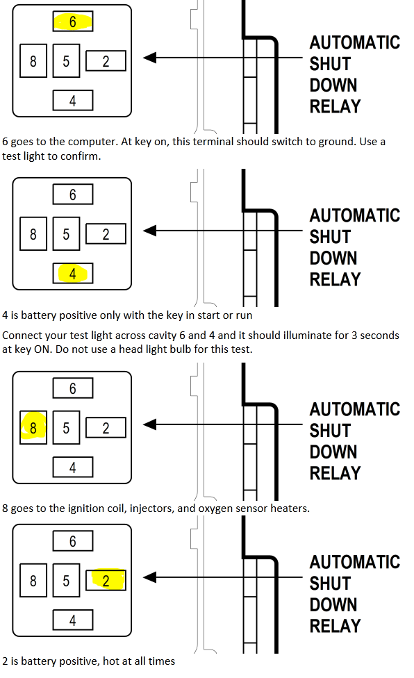
I spent time this afternoon checking voltages at the ASD. It would appear that perhaps this is telling where the issue. Battery was down to testing, measured 12.21 volts.
With ASD relay pulled I measured the pin/cavities, first set with the key off (actually pulled)
C2– 12.40 volts
C4– 0 MV
C6– 1.1-.05 MV (seemed to keep dropping but stopped at .05 MV
C8– 0 MV
With Key on:
C2–12.19 volts
C4– 11.96 volts
C6– .8 MV
C8–3.0 MV (I did not think to try measuring with the engine cranking, would that make a difference on C8?)
I measured the voltage at the coil connector with the connector pulled from the coil:
The DG/OR wire—Pin #2 according to the diagram— 3.0MV
The GY wire— Pin #1 that goes to PCM A7–10MV
There was no 12+ volts on ASD C8 or at DG/OR wire at Pin 2 at the disconnected coil. It would appear that this is significant, if it is how do I find what is causing the lack of voltage from C8? How do you find the cause?
Please Log in or Create an account to join the conversation.
- ferris48
-
- Offline
- Premium Member
-
- Posts: 129
- Thank you received: 47
Everything else looks good.
Please Log in or Create an account to join the conversation.
- simclardy
-
- Offline
- Senior Member
-
- Posts: 78
- Thank you received: 7
Sent from my SM-G970U using Tapatalk
Please Log in or Create an account to join the conversation.
- mmorris923
-
Topic Author
- Offline
- Junior Member
-
- Posts: 35
- Thank you received: 1
Buyer beware of new parts … There just might possibly be a solution to the 97 mystery! Our mechanic and his father made a house/ranch call today and they may have discovered the problem. First of all for some reason the old 1986 coil once again began working which totally mystified them. The new OEM MOPAR still wouldn’t work. In further tests the 86 coil stopped working! The new replacement connector from Summit was taken apart and it was discovered that the female ground cavity the coil pin plugged into was pulled back almost a 1/4” . Upon closer examination it was decided that the 1986 coil’s pins appeared to be a little thicker and possibly a tad longer. That may have made the difference to allow the 86 coil to make contact where as the newer coils couldn’t make contact. Now it is a matter of trying to find a better replacement connector for the coil. Right now, today we have the coil zip tied together to hold the connector tight to keep the connection until a permanent fix can be made.
The new connector was installed when the OEM connector was discovered to cause stalling when it was wiggled. The OEM connector probably was the cause of the intermittent stalling and when the new connector was installed then the coil was not able to make contact and fire the engine.
I want to thank everyone for your time and suggestions for testing the mystery. I will endeavor to come back in a month or so and give a final update hopefully with no further issues. It is frustrating when one buys a new part only to latter find out the new part ended up creating a problemu
Please Log in or Create an account to join the conversation.
- simclardy
-
- Offline
- Senior Member
-
- Posts: 78
- Thank you received: 7
Sounds like you got it!
Cheers
Sent from my SM-G970U using Tapatalk
Please Log in or Create an account to join the conversation.
- juergen.scholl
-

- Offline
- Platinum Member
-

- Active partschanger
- Posts: 1230
- Thank you received: 462
An expert is someone who knows each time more on each time less, until he finally knows absolutely everything about absolutely nothing.
Please Log in or Create an account to join the conversation.