Help us help you. By posting the year, make, model and engine near the beginning of your help request, followed by the symptoms (no start, high idle, misfire etc.) Along with any prevalent Diagnostic Trouble Codes, aka DTCs, other forum members will be able to help you get to a solution more quickly and easily!
Jeep 4.0 Secondary Ignition Waveform questions
- Graveydavey
-
 Topic Author
- Offline
- New Member
-

Less
More
- Posts: 18
- Thank you received: 2
3 years 4 months ago #58836
by Graveydavey
Replied by Graveydavey on topic Jeep 4.0 Secondary Ignition Waveform questions
Is it normal for the firing line voltage to drop during a throttle snap?
Looking over these two waveforms again. I don't get what's going on. Why such different results?
Looking over these two waveforms again. I don't get what's going on. Why such different results?
Please Log in or Create an account to join the conversation.
- Chad
-

- Offline
- Moderator
-

- I am not a parts changer.
Less
More
- Posts: 2161
- Thank you received: 725
3 years 4 months ago - 3 years 4 months ago #58839
by Chad
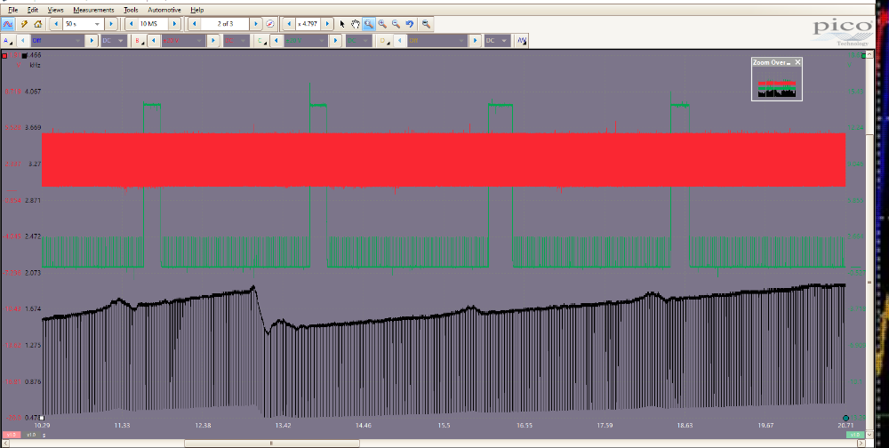
When I felt the shudder, I manually pulsed a PowerProbe and captured it on the Green channel. The Black trace is the Crankshaft frequency, as I am accelerating. The big drop in the Black trace is a Gear change.
I believe, you are still under-sampling. You should be somewhere in the range of 1-3 million samples per second.
"Knowledge is a weapon. Arm yourself, well, before going to do battle."
"Understanding a question is half an answer."
I have learned more by being wrong, than I have by being right.")
Replied by Chad on topic Jeep 4.0 Secondary Ignition Waveform questions
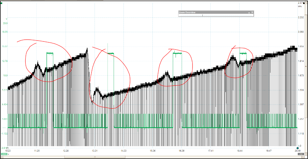
If you capture a waveform of the crankshaft position sensor, you can use the frequency of the signal to determine if the "fish-bite" is a misfire, or Torque Converter shudder. When you feel the "stumble", If it is a misfire, the frequency will drop. If it is TC shudder, the frequency will rise. Here is an image of crankshaft frequency with a vehicle with TC shudder.I drove the car again to play around the torque converter lockup. I wired in a switch that would cut the signal to lock up the torque converter. What I noticed was that that the stumble seems to be less when the torque converter isn't locked. It's still there, but its like the torque converter is cushioning it. That thought leads me back to a problem with the motor.
When I felt the shudder, I manually pulsed a PowerProbe and captured it on the Green channel. The Black trace is the Crankshaft frequency, as I am accelerating. The big drop in the Black trace is a Gear change.
Is it normal for the firing line voltage to drop during a throttle snap? Looking over these two waveforms again. I don't get what's going on. Why such different results?
I believe, you are still under-sampling. You should be somewhere in the range of 1-3 million samples per second.
"Knowledge is a weapon. Arm yourself, well, before going to do battle."
"Understanding a question is half an answer."
I have learned more by being wrong, than I have by being right.
Last edit: 3 years 4 months ago by Chad.
The following user(s) said Thank You: juergen.scholl
Please Log in or Create an account to join the conversation.
- Graveydavey
-
Topic Author
- Offline
- New Member
-
Less
More
- Posts: 18
- Thank you received: 2
3 years 4 months ago - 3 years 4 months ago #58845
by Graveydavey
Replied by Graveydavey on topic Jeep 4.0 Secondary Ignition Waveform questions
Thanks, Chad. A fish bite is a great description for this problem. I'll try this test tomorrow.
Last edit: 3 years 4 months ago by Graveydavey. Reason: grammar
Please Log in or Create an account to join the conversation.
- Graveydavey
-
Topic Author
- Offline
- New Member
-
Less
More
- Posts: 18
- Thank you received: 2
3 years 4 months ago #58856
by Graveydavey
Replied by Graveydavey on topic Jeep 4.0 Secondary Ignition Waveform questions
My attempt at capturing the crankshaft position sensor while the fish bite was happening didn't reveal much. Nothing dramatic like yours. I'm still learning how to manipulate these time and voltage settings.
Please Log in or Create an account to join the conversation.
- Graveydavey
-
Topic Author
- Offline
- New Member
-
Less
More
- Posts: 18
- Thank you received: 2
3 years 3 months ago - 3 years 3 months ago #59063
by Graveydavey
Replied by Graveydavey on topic Jeep 4.0 Secondary Ignition Waveform questions
I've been studying up a bit on fuel pump current testing, but the waveforms I'm getting don't look anything close to what a good pump looks like. Am I doing this right? I have a Fluke i410 clamp and I created a new probe in Picoscope for it. I set resolution for 10.5 bits because I'm getting a lot of noise. I think I have a bad fuel pump. Could anyone provide a second opinion for me? Thank you!
Last edit: 3 years 3 months ago by Graveydavey. Reason: to add the attachment and grammar
Please Log in or Create an account to join the conversation.
- Chad
-
- Offline
- Moderator
-
- I am not a parts changer.
Less
More
- Posts: 2161
- Thank you received: 725
3 years 3 months ago - 3 years 3 months ago #59080
by Chad
That is a good crank capture. And it is a good start.")
(However, you have AC coupling selected. Even though the crank signal is an AC sine-wave, you should use DC coupling. AC coupling will hide the base voltage of the waveform. AC coupling is, primarily, used as a zoom feature. Pico's zoom capabilities are so good that AC coupling is, rarely, needed.)
The image that I posted was not a raw capture of the crank signal. It was the FREQUENCY of the Crank signal...an average of how fast the crank signal cycled from high to low, created with a "Math Channel".
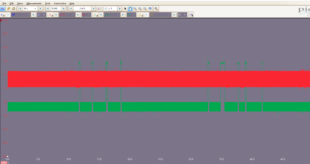
The raw capture looks like this, WITHOUT the frequency math channel:
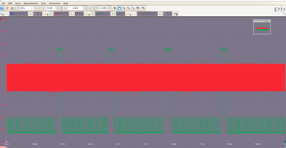
This is the same zoom level as the image of the PROCESSED FREQUENCY that I, previously, posted:
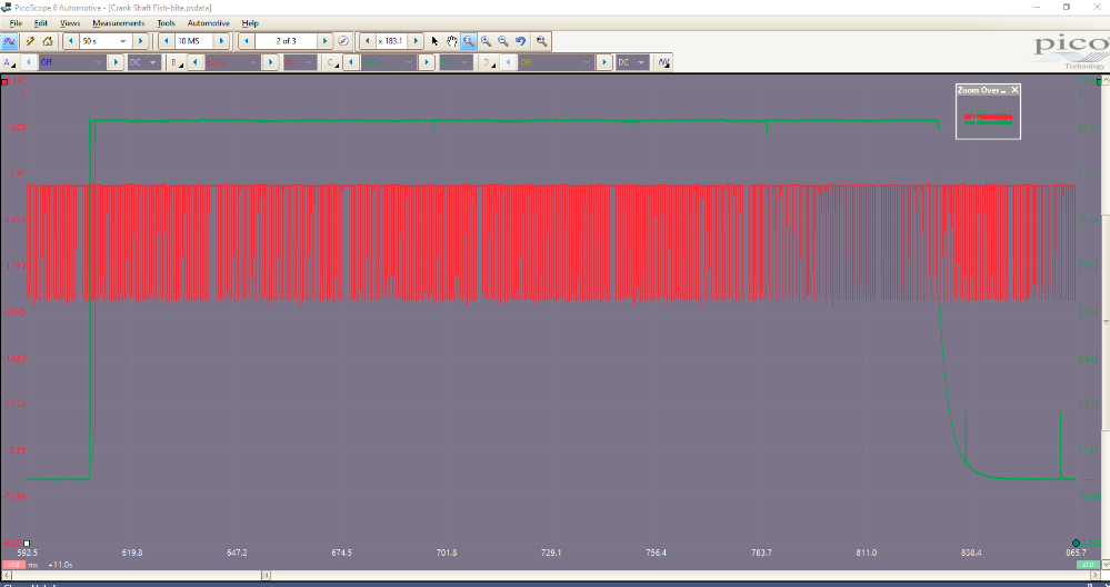
This is zoomed to inside of one of the green power probe pulses, which is close to the zoom level of your capture:
"Knowledge is a weapon. Arm yourself, well, before going to do battle."
"Understanding a question is half an answer."
I have learned more by being wrong, than I have by being right.
Replied by Chad on topic Jeep 4.0 Secondary Ignition Waveform questions
My attempt at capturing the crankshaft position sensor while the fish bite was happening didn't reveal much. Nothing dramatic like yours. I'm still learning how to manipulate these time and voltage settings.
That is a good crank capture. And it is a good start.
(However, you have AC coupling selected. Even though the crank signal is an AC sine-wave, you should use DC coupling. AC coupling will hide the base voltage of the waveform. AC coupling is, primarily, used as a zoom feature. Pico's zoom capabilities are so good that AC coupling is, rarely, needed.)
The image that I posted was not a raw capture of the crank signal. It was the FREQUENCY of the Crank signal...an average of how fast the crank signal cycled from high to low, created with a "Math Channel".
The raw capture looks like this, WITHOUT the frequency math channel:
This is the same zoom level as the image of the PROCESSED FREQUENCY that I, previously, posted:
This is zoomed to inside of one of the green power probe pulses, which is close to the zoom level of your capture:
"Knowledge is a weapon. Arm yourself, well, before going to do battle."
"Understanding a question is half an answer."
I have learned more by being wrong, than I have by being right.
Last edit: 3 years 3 months ago by Chad.
Please Log in or Create an account to join the conversation.
- Chad
-
- Offline
- Moderator
-
- I am not a parts changer.
Less
More
- Posts: 2161
- Thank you received: 725
3 years 3 months ago #59081
by Chad
"Knowledge is a weapon. Arm yourself, well, before going to do battle."
"Understanding a question is half an answer."
I have learned more by being wrong, than I have by being right.
Replied by Chad on topic Jeep 4.0 Secondary Ignition Waveform questions
Here, is a screenshot of the raw crank signal AND the processed Frequency:
Here , is another thread that discusses Crank frequency.
Here , is a video that is well worth watching.
Here , is another thread that discusses Crank frequency.
Here , is a video that is well worth watching.
"Knowledge is a weapon. Arm yourself, well, before going to do battle."
"Understanding a question is half an answer."
I have learned more by being wrong, than I have by being right.
Please Log in or Create an account to join the conversation.
- Chad
-
- Offline
- Moderator
-
- I am not a parts changer.
Less
More
- Posts: 2161
- Thank you received: 725
3 years 3 months ago #59085
by Chad
You could put a little more time on the screen. I'd step out to 10ms/Div. Or, maybe, more to get a bigger picture. But, :woohoo: that is an ugly waveform!
If you are unsure of your settings or the pattern that you are seeing, try to capture the heater blower motor waveform. They are, usually, easy to access. And the settings are, basically, the same. A motor, is a motor.
"Knowledge is a weapon. Arm yourself, well, before going to do battle."
"Understanding a question is half an answer."
I have learned more by being wrong, than I have by being right.
Replied by Chad on topic Jeep 4.0 Secondary Ignition Waveform questions
I've been studying up a bit on fuel pump current testing, but the waveforms I'm getting don't look anything close to what a good pump looks like. Am I doing this right? I have a Fluke i410 clamp and I created a new probe in Picoscope for it. I set resolution for 10.5 bits because I'm getting a lot of noise. I think I have a bad fuel pump. Could anyone provide a second opinion for me? Thank you!
You could put a little more time on the screen. I'd step out to 10ms/Div. Or, maybe, more to get a bigger picture. But, :woohoo: that is an ugly waveform!
If you are unsure of your settings or the pattern that you are seeing, try to capture the heater blower motor waveform. They are, usually, easy to access. And the settings are, basically, the same. A motor, is a motor.
"Knowledge is a weapon. Arm yourself, well, before going to do battle."
"Understanding a question is half an answer."
I have learned more by being wrong, than I have by being right.
Please Log in or Create an account to join the conversation.
- Graveydavey
-
Topic Author
- Offline
- New Member
-
Less
More
- Posts: 18
- Thank you received: 2
3 years 3 months ago #59091
by Graveydavey
Replied by Graveydavey on topic Jeep 4.0 Secondary Ignition Waveform questions
Thank you for all of your help, Chad. I tested the blower motor as you suggested and I got a typical motor current waveform. From that I assume that my fuel pump waveform was valid so I'll be putting a new pump tomorrow hopefully.
The fishbite has gotten much worse. Happening at all speeds under load. I don't drive the Jeep much. I would guess that I've gone about 500 miles since this problem first started showing up.
The fishbite has gotten much worse. Happening at all speeds under load. I don't drive the Jeep much. I would guess that I've gone about 500 miles since this problem first started showing up.
Please Log in or Create an account to join the conversation.
Time to create page: 0.561 seconds