Using Waveforms to Identify a misfiring cylinder.
- Chad
-
 Topic Author
- Offline
- Moderator
-

- I am not a parts changer.
- Posts: 2199
- Thank you received: 741
1999 Ford F150, 5.4L.
Noticeable, somewhat intermittent misfire. Misfire Monitor flags no misfires. No Codes. Fuel trim data indicates the misfire is on Bank 1.
Spark Plugs, Coils, Injectors, Fuel Filter, and Air Filter have all been replaced. Relative Compression looks, relatively, good. How would you tackle it? Here are a couple, different ways.
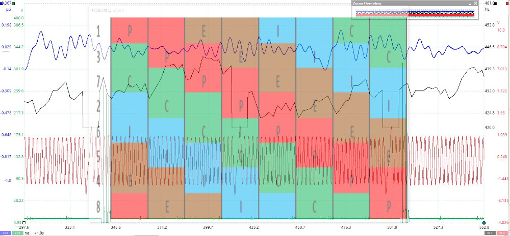
This waveform contains all the information needed to identify which cylinder is misfiring.
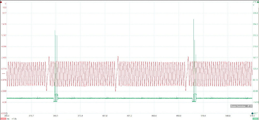
RED = Crank Signal
GREEN = #1 Primary Voltage
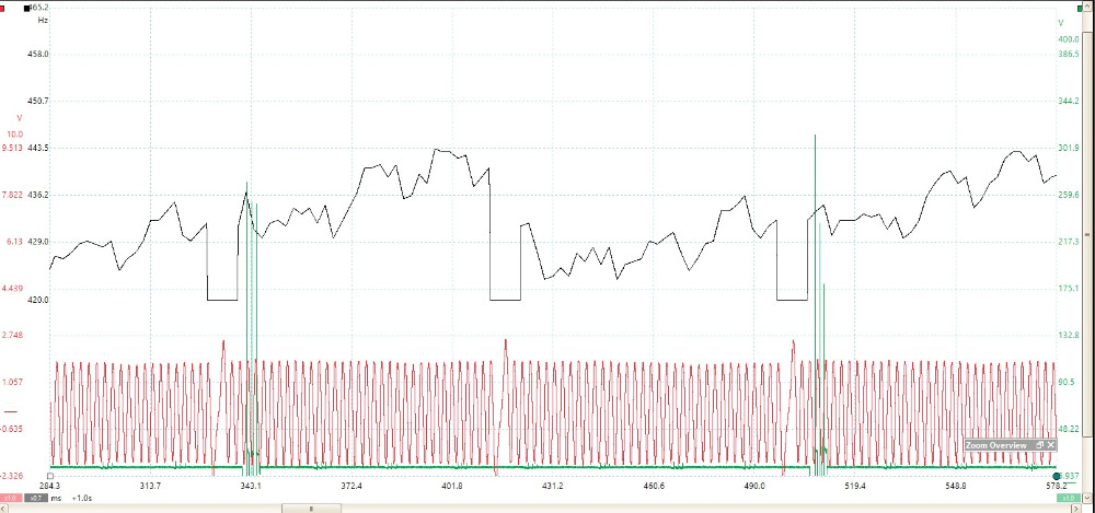
If we add Crankshaft Frequency, (BLACK Trace) by creating a "Math Channel", we can see the Crankshaft slow down, due to the misfire.
*ignore the HUGE drop-out in the BLACK trace. That is caused by the missing "Sync Notch". The Math Channel interprets the missing tooth as a BIG speed reduction.
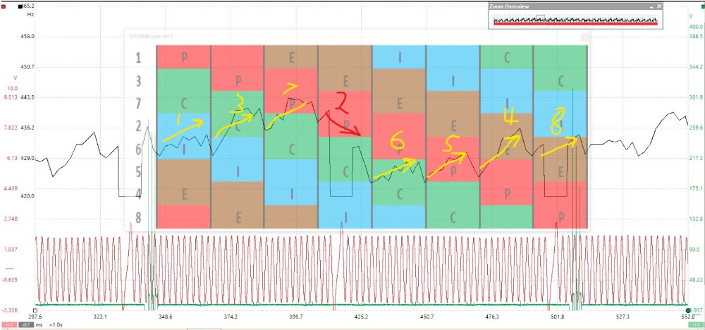
Adding a Piston Position Chart, we can see the Frequency of the Crankshaft increase with each Power Stroke, except Cylinder #2. The Crankshaft slows down during #2 Power Stroke, indicating insufficient combustion.
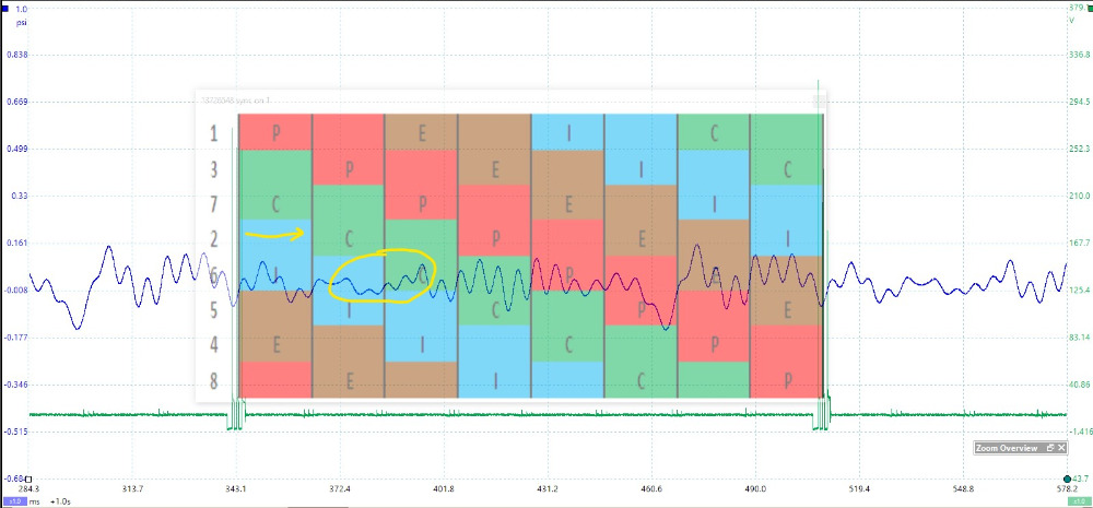
This image contains all the information needed to identify which cylinder is misfiring AND indicates which Valve is at Fault.
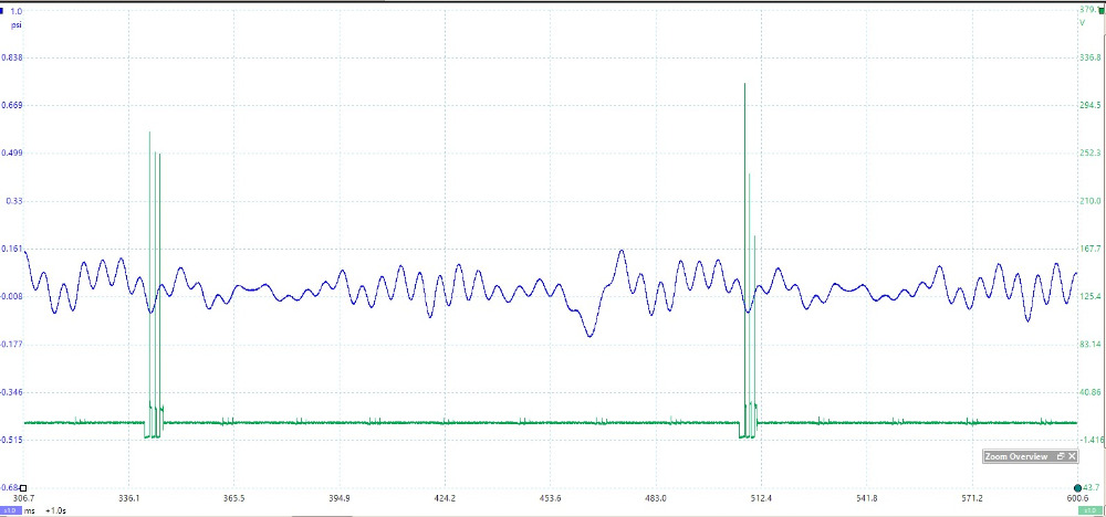
BLUE = Pressure Transducer in the Tailpipe
GREEN = Cylinder #1 Ignition Coil Primary Voltage
*This is a RUNNING @ Idle Waveform*
Using a Piston Position Chart, we can see that when the #2 Exhaust Valve opens, the BLUE trace falls into a vacuum. This indicates a misfire on Cylinder #2. (Remember the Old-School "Dollar Bill Trick"?)
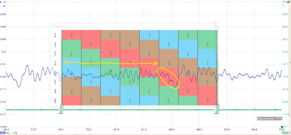
The BLUE Trace has another anomaly, too. Notice that, when Cylinder #2 comes up on Compression, Tailpipe pressure, slightly, rises instead of the normal oscillation. This indicates that Cylinder #2 exhaust valve is leaking.
A Picture is Worth a Thousand Words.
"Knowledge is a weapon. Arm yourself, well, before going to do battle."
"Understanding a question is half an answer."
I have learned more by being wrong, than I have by being right.

Please Log in or Create an account to join the conversation.
- Chad
-
Topic Author
- Offline
- Moderator
-
- I am not a parts changer.
- Posts: 2199
- Thank you received: 741
drive.google.com/file/d/1g-_p5PPNMu2u5E9...YF2/view?usp=sharing
"Knowledge is a weapon. Arm yourself, well, before going to do battle."
"Understanding a question is half an answer."
I have learned more by being wrong, than I have by being right.
Please Log in or Create an account to join the conversation.
- Noah
-

- Offline
- Moderator
-
- Posts: 5058
- Thank you received: 1126
I'm having a hard time seeing the frequency change in the black trace, it looks to me as if it lines up with the sync notch every time.
Would you care to elaborate on that aspect of the waveform a little further for me?
I'm wishing more and more that my Snap On scope could keep up with that Pico software...
Please Log in or Create an account to join the conversation.
- Matt T
-

- Offline
- Platinum Member
-

- Posts: 751
- Thank you received: 276
Noah wrote: Impressive, as always Chad!
I'm having a hard time seeing the frequency change in the black trace, it looks to me as if it lines up with the sync notch every time.
Would you care to elaborate on that aspect of the waveform a little further for me?
I'm wishing more and more that my Snap On scope could keep up with that Pico software...
Like Chad said ignore the sync notch dropouts themselves. The frequencies either side of them shows the rpm dropping on the bad cylinder.
Please Log in or Create an account to join the conversation.
- Chad
-
Topic Author
- Offline
- Moderator
-
- I am not a parts changer.
- Posts: 2199
- Thank you received: 741
Noah wrote: I'm having a hard time seeing the frequency change in the black trace, it looks to me as if it lines up with the sync notch every time.
Would you care to elaborate on that aspect of the waveform a little further for me?
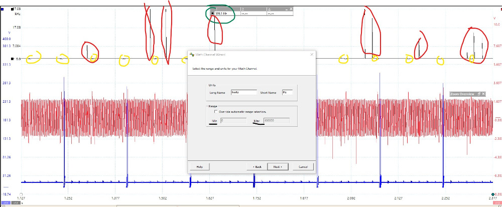
This is a picture of the Frequency Math Channel at it's default Range (zoom level).
The Black trace is the Crank Frequency. The upward spikes (RED) can be ignored. With some filtering on the Crank signal, these will disappear. The YELLOW circles are the Sync notches. They are, merely, bumps at this zoomed out range.
The over-all Frequency of the Crankshaft signal is 389.1 Hz (GREEN).
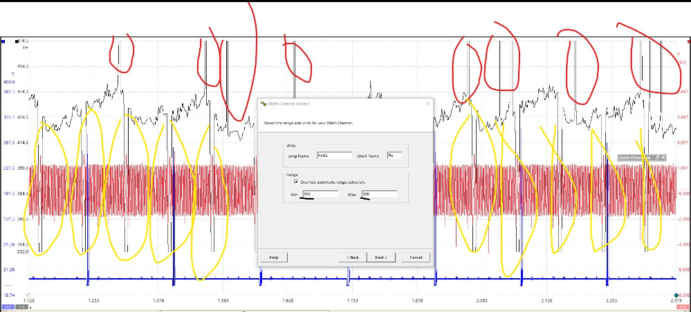
If we edit the Frequency Range to a Min/Max of just below/above the overall frequency, we can Zoom in. The upward spikes (RED) can still be ignored. The HUGE downward spikes (YELLOW) are the Sync Notches and should be ignored. Comparing the little (yellow) bumps, from the above image, to the HUGE (yellow) downward spikes in this image, show how far in we are zoomed. Ignore the sync notches.
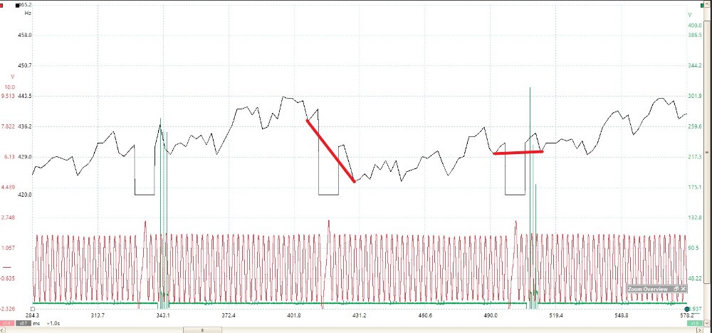
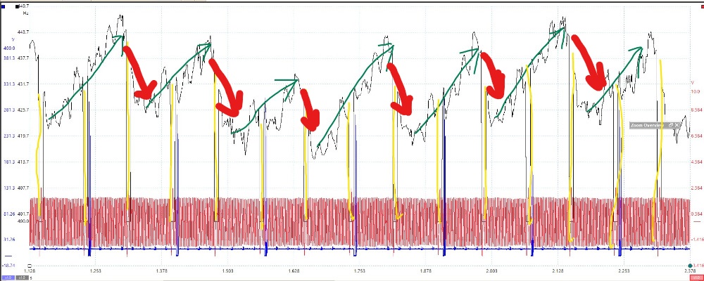
This next image is zoomed in a little farther on the frequency. It has some filtering on the crank signal. This eliminated the upward spikes. Here, we can clearly see a repeating upward pattern (GREEN), indicating Crank acceleration. In RED, we see the downward Deceleration, due to the misfire.
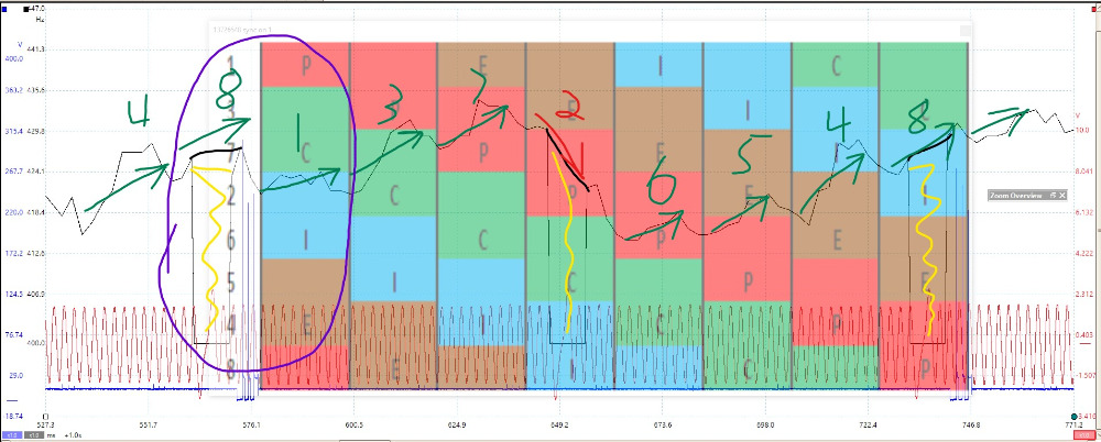
Zooming in farther and adding the Piston Position chart, we can see that the pattern repeats its downward deceleration at Cylinder #2 Power Stroke (RED) . All other Cylinders show an increase (GREEN) in frequency during Power Stroke.
What I have circled in PURPLE looks like the frequency dropped from Cyl #8 to Cyl #1. It didn't. This is an illusion created by the sync notch. Ignore the sync notch.
"Knowledge is a weapon. Arm yourself, well, before going to do battle."
"Understanding a question is half an answer."
I have learned more by being wrong, than I have by being right.
Please Log in or Create an account to join the conversation.
- Chad
-
Topic Author
- Offline
- Moderator
-
- I am not a parts changer.
- Posts: 2199
- Thank you received: 741
Noah wrote: I'm wishing more and more that my Snap On scope could keep up with that Pico software...
Save your money.
Still, love my Verus, too.
"Knowledge is a weapon. Arm yourself, well, before going to do battle."
"Understanding a question is half an answer."
I have learned more by being wrong, than I have by being right.
Please Log in or Create an account to join the conversation.
- Noah
-
- Offline
- Moderator
-
- Posts: 5058
- Thank you received: 1126
To me it looked like the only reason there was an appreciable drop in the CKP frequency was from the sync notch and the pattern just ratcheted up until the sync notch appeared again.
Especially since the the sync notch and subsequent drop out aligned with the suspect #2 cylinder.
The zoomed out and annotated capture helped me see it much more clearly. I still don't know that I'd be able to pick that out of a live capture to make a positive diagnosis.
I've said it before and I'll say it again, you are the man Chad!
Please Log in or Create an account to join the conversation.
- Chad
-
Topic Author
- Offline
- Moderator
-
- I am not a parts changer.
- Posts: 2199
- Thank you received: 741
Especially since the the sync notch and subsequent drop out aligned with the suspect #2 cylinder.
This messed me up, too. I, originally, thought that I had a misfire on Clinder #8, too. Paul (not Danner) helped me see my error.
I had only heard about creating a frequency trace with a Math Channel to identify misfires. This was the first time that I have used it.
I think it opens up a new door for MAF sensors, too. I'm itching for a MAF problem.:lol:
I still don't know that I'd be able to pick that out of a live capture to make a positive diagnosis.
No one could. You need to save the capture and, then, analyze it using a Lay-over, Cursors, and Zooming.
"Knowledge is a weapon. Arm yourself, well, before going to do battle."
"Understanding a question is half an answer."
I have learned more by being wrong, than I have by being right.
Please Log in or Create an account to join the conversation.
- Paul P.
-

- Offline
- Platinum Member
-
- Posts: 457
- Thank you received: 195
This is a 2016 GMC Sierra 5.3 @ WOT climbing a 7% Grade.
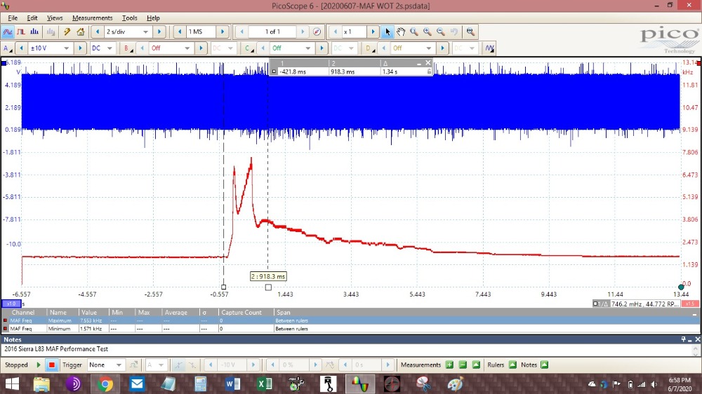
MAF maxed out @ 7.5kHz which is spec.
"Paul"
Never stop Learning.
Please Log in or Create an account to join the conversation.
- Chad
-
Topic Author
- Offline
- Moderator
-
- I am not a parts changer.
- Posts: 2199
- Thank you received: 741
Weycraze wrote: Awesome Thread Chad !!! lol
"Paul"
Thank you, Paul (not Danner)!
And, thanks for your help!
"Knowledge is a weapon. Arm yourself, well, before going to do battle."
"Understanding a question is half an answer."
I have learned more by being wrong, than I have by being right.
Please Log in or Create an account to join the conversation.
- Tyler
-

- Offline
- Moderator
-
- Full time HACK since 2012
- Posts: 6129
- Thank you received: 1545
I'd happily watch more from Adam Robertson. He's actually got a class in the upcoming ATE Expo:
www.atetrainingexpo.com/training
Please Log in or Create an account to join the conversation.
- Chad
-
Topic Author
- Offline
- Moderator
-
- I am not a parts changer.
- Posts: 2199
- Thank you received: 741
"Knowledge is a weapon. Arm yourself, well, before going to do battle."
"Understanding a question is half an answer."
I have learned more by being wrong, than I have by being right.
Please Log in or Create an account to join the conversation.
- Tyler
-
- Offline
- Moderator
-
- Full time HACK since 2012
- Posts: 6129
- Thank you received: 1545
Chad wrote: LMAO, Tyler! I love your Avatar! :lol: :lol: :lol:
HE JUST LOOKS SO ANGRY. :lol: I can't wait till Paul swings by and notices.
Please Log in or Create an account to join the conversation.
- Matt T
-
- Offline
- Platinum Member
-
- Posts: 751
- Thank you received: 276
Tyler wrote:
Chad wrote: LMAO, Tyler! I love your Avatar! :lol: :lol: :lol:
HE JUST LOOKS SO ANGRY. :lol: I can't wait till Paul swings by and notices.
That green tint to it looks like he's turning into the Hulk :lol: :lol: :lol:
Please Log in or Create an account to join the conversation.
- Chad
-
Topic Author
- Offline
- Moderator
-
- I am not a parts changer.
- Posts: 2199
- Thank you received: 741
Matt T wrote: That green tint to it looks like he's turning into the Hulk :lol: :lol: :lol:
I was thinking Shrek. :lol:
"Knowledge is a weapon. Arm yourself, well, before going to do battle."
"Understanding a question is half an answer."
I have learned more by being wrong, than I have by being right.
Please Log in or Create an account to join the conversation.
- AguilarPro
-
- Offline
- Junior Member
-

- Posts: 21
- Thank you received: 2
 . The reason I want the Pico is because it can be trusted as opposed to other cheap scopes which sometimes you are not sure about and have to use another gage just for kicks.
 Please Log in or Create an account to join the conversation.