DIY Pressure Transducer
- SailorBob
-

- Offline
- Elite Member
-

www.scannerdanner.com/forum/post-your-re...i-at-idle.html#20351
Please Log in or Create an account to join the conversation.
- Sooknanan
-

- Offline
- New Member
-

- Posts: 17
- Thank you received: 5
Please Log in or Create an account to join the conversation.
- SailorBob
-
- Offline
- Elite Member
-
Please Log in or Create an account to join the conversation.
- Sooknanan
-
- Offline
- New Member
-
- Posts: 17
- Thank you received: 5
I know the diy pressure transducers will with the pico 6 software.
But what I am asking is if the pico diagnostics software would recognize a diy p/t while conducting a compression test and populate for each cylinder.

Sent from my iPhone using Tapatalk
Please Log in or Create an account to join the conversation.
- Andy.MacFadyen
-

- Offline
- Moderator
-

- Posts: 3357
- Thank you received: 1037
Sooknanan wrote: (null)
I know the diy pressure transducers will with the pico 6 software.
But what I am asking is if the pico diagnostics software would recognize a diy p/t while conducting a compression test and populate for each cylinder.
Sent from my iPhone using Tapatalk
But pressure sensors aren't used for relative compression tests they are done be either an amp clamp on the starter cable or by the battery voltage method. The Pico software should have no problem with working on battery cranking voltage to give a measure of starter current.
From the Pico Automotive Website
" We're trying to plug a hole in the universe, what are you doing ?. "
(Walter Bishop Fringe TV show)
Please Log in or Create an account to join the conversation.
- Sooknanan
-
- Offline
- New Member
-
- Posts: 17
- Thank you received: 5
Please Log in or Create an account to join the conversation.
- SailorBob
-
- Offline
- Elite Member
-
Please Log in or Create an account to join the conversation.
- Andy.MacFadyen
-
- Offline
- Moderator
-
- Posts: 3357
- Thank you received: 1037
One thing to be aware of with cranking voltage compression testing is old style starters tend to have much higher current draw than more modern starters which can be both geared and be the permanent magnet type.
Other thing to watch for is the number of cylinders --- 3 cylinder 4 strokes
" We're trying to plug a hole in the universe, what are you doing ?. "
(Walter Bishop Fringe TV show)
Please Log in or Create an account to join the conversation.
- bruce.oliver
-

- Offline
- Elite Member
-
- Posts: 318
- Thank you received: 88
Please Log in or Create an account to join the conversation.
- Andy.MacFadyen
-
- Offline
- Moderator
-
- Posts: 3357
- Thank you received: 1037
" We're trying to plug a hole in the universe, what are you doing ?. "
(Walter Bishop Fringe TV show)
Please Log in or Create an account to join the conversation.
- bruce.oliver
-
- Offline
- Elite Member
-
- Posts: 318
- Thank you received: 88
Please Log in or Create an account to join the conversation.
- SailorBob
-
- Offline
- Elite Member
-
Please Log in or Create an account to join the conversation.
- bruce.oliver
-
- Offline
- Elite Member
-
- Posts: 318
- Thank you received: 88
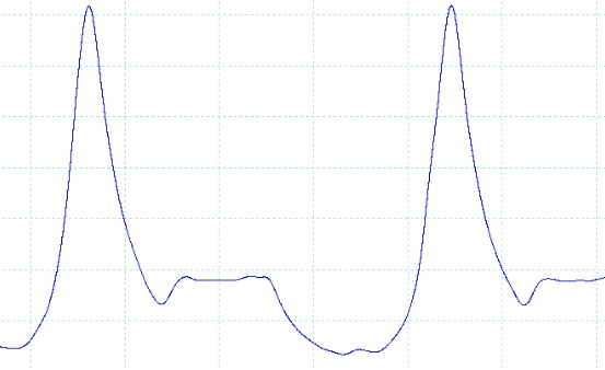
SailorBob wrote: Set the pico to use 1 khz low pass filtering and that should clean it up. You're just seeing electrical noise probably.
It's not noise. I am used to seeing that on waveforms. It's like Andy described, distinct steps in the waveform. Like the transducer responds to slow for the software.
Please Log in or Create an account to join the conversation.
- ShaoLin68
-
- Offline
- New Member
-
- Posts: 3
- Thank you received: 2
I am making a dedicated set of transducers myself that will be able to be used with either a pico or a verus..
15psi for Vacuum (which converts to 30 in Hg, which is what a regular vacuum gauge reads anyway),
150psi for fuel pressure (a fuel pressure gauge goes up to 140psi),
300psi for Gas engine compression (which is what a regualar gauge goes to),
and a 1000psi for Diesel engine compression (which is what a diesel compression gauge goes to.. Im a truck driver, I had to make one for trucks.. LOL)
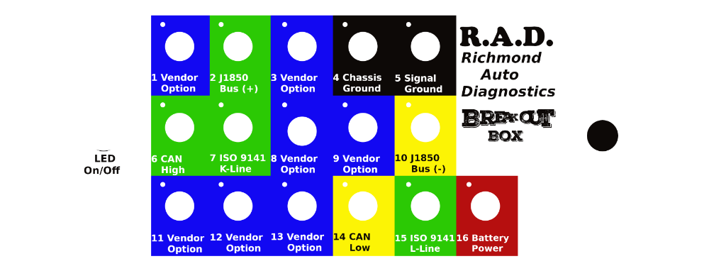
over the Thanksgiving holiday, I am going to build the ones I have the stuff for so far.. for the electrical, I am using battery power/ground, then going to a 12v/5v stepdown to supply the transducers with the correct voltage.. there will be an LED at the power plug to let you know there is power, and an LED at the signal out to let you know there is signal going to the scope..
I will then post some videos showing them, and showing how to use them so you get the best results.. I dont have access to a verus but I will be testing it on a Hantek 1008C.. I have a 98 Infiniti I30 that will be my test mule..
but that wont be for another month and a half.. I just wanted to point out that the transducers use a 5v and produce a 0psi reading at 0.5v and maximum psi reading at 4.5.. have a good day..
heres a sneek peek at the labels..


Please Log in or Create an account to join the conversation.
- SailorBob
-
- Offline
- Elite Member
-
Please Log in or Create an account to join the conversation.
- Andy.MacFadyen
-
- Offline
- Moderator
-
- Posts: 3357
- Thank you received: 1037
" We're trying to plug a hole in the universe, what are you doing ?. "
(Walter Bishop Fringe TV show)
Please Log in or Create an account to join the conversation.
- SailorBob
-
- Offline
- Elite Member
-
Please Log in or Create an account to join the conversation.
- Andy.MacFadyen
-
- Offline
- Moderator
-
- Posts: 3357
- Thank you received: 1037
SailorBob wrote: I wouldn't say it doesn't matter - what you need to pay attention to is the Nyquist sampling rate - basically to accurate render the signal, in this case pressure changes, you need a transducer that can respond twice as fast as the signal changes. In dry air at 20*C air pressure changes propagate at the speed of sound, 343.2 m / s , which works out to 3.4 centimeters per millisecond. Or 1.34 inches per millisecond. So for in cylinder pressure readings I'd look for a transducer with at least a one millisecond response time, or really maybe even a little faster than that. Practically speaking, the one I use is rated one millisecond and it seems to produce good waveforms. When paired with 1 khz lpf I get nicely detailed clean waveforms.
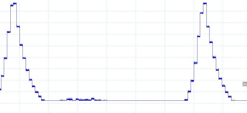
Nothing to do with the sampling rate, in fact the steps are only really noticeable when the change is pressure is slow .
Take for a example a sensor rated at 250 psi ---- a sensor with 8 bit internal processing will only have 255 possible analogue output voltages so it will work in steps of approximately 1 psi.
On a 250 psi sensor a resolution of 1 psi steps is better than 0.5% of full scale is more than is required in any real world application.
But by matching the sensors max full scale range to what is being measure the size of the step change in output voltage is reduced choosing 100 psi sensor for running compression tests will improve the step resolution to 0.4 psi, but won't read high enough pressure for cranking compression tests which normally require around 200psi on older gasoline engines and can be 10 to 20% higher on GDI units.
It is of course fairly easy to smooth out the step changes with either an RC filter on wiring between the sensor and scope or on a scope with inbuilt software filters using a low pass filter but detail will be lost.
" We're trying to plug a hole in the universe, what are you doing ?. "
(Walter Bishop Fringe TV show)
Please Log in or Create an account to join the conversation.
- Sooknanan
-
- Offline
- New Member
-
- Posts: 17
- Thank you received: 5
Are any of my settings wrong that can cause this or should I just buy the transducer from the ebay link provided on page 1. Thanks in advance.
Please Log in or Create an account to join the conversation.
- Andy.MacFadyen
-
- Offline
- Moderator
-
- Posts: 3357
- Thank you received: 1037
" We're trying to plug a hole in the universe, what are you doing ?. "
(Walter Bishop Fringe TV show)
Please Log in or Create an account to join the conversation.