Testing fuel injectors with a knock sensor
- Andy.MacFadyen
-

- Offline
- Moderator
-

- Posts: 3357
- Thank you received: 1037
The frequency range of the injectors pintel movement "click" is roughly in the range 2.5khz to 10khz. I have experimented with various software filters but the back ground noise on the trace on a running engine has the same frequency so I suspect the noise on the trace is actually due to echoes within the fuel rail.
" We're trying to plug a hole in the universe, what are you doing ?. "
(Walter Bishop Fringe TV show)
Please Log in or Create an account to join the conversation.
- Andy.MacFadyen
-
- Offline
- Moderator
-
- Posts: 3357
- Thank you received: 1037
I would preffer this test over a FirstLook sensor on the fuel rail pulse damper..
" We're trying to plug a hole in the universe, what are you doing ?. "
(Walter Bishop Fringe TV show)
Please Log in or Create an account to join the conversation.
- Tyler
-
 Topic Author
- Offline
- Moderator
-
- Full time HACK since 2012
- Posts: 6129
- Thank you received: 1544
Andy.MacFadyen wrote: would preffer this test over a FirstLook sensor on the fuel rail pulse damper..
Totally agree here. I find this method to be much easier to interpret, with less work required. But, like you said, we then get into noise and background interference
Please Log in or Create an account to join the conversation.
- Tyler
-
Topic Author
- Offline
- Moderator
-
- Full time HACK since 2012
- Posts: 6129
- Thank you received: 1544
Got the chance to play with this on a Chrysler Sebring, 2.7L. Customer complaining of a misfire, and it actually had a #5 injector code stored. Really, the diagnosis was pretty straightforward, but I wanted to have a look anyway.
The trick here is that this engine uses plastic fuel rails (one for each bank), with a metal tube connecting between them. This ended up changing the quality of the waveform quite a bit.
Here's what I ended up with during the misfire. The knock sensor is up against the metal pipe in this capture, triggered off #2, firing order 1-2-3-4-5-6.
Admittedly, this one is very tough to call useable.
So, it doesn't work perfectly in every scenario. Variables, always variables. :lol:
Please Log in or Create an account to join the conversation.
- Andy.MacFadyen
-
- Offline
- Moderator
-
- Posts: 3357
- Thank you received: 1037
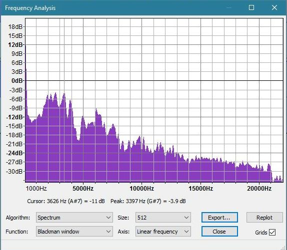
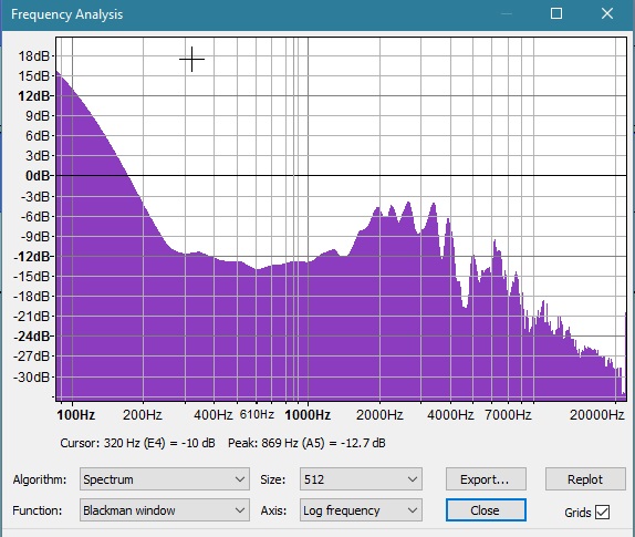
Most of the sound lies between 1500 and 8000hz which probably explains why most of the knock sensors wouldn't work for Tyler as from info on the web it seems most older style knock sensors are tuned to narow frequency band around 10,000 to 11,000 hz.
" We're trying to plug a hole in the universe, what are you doing ?. "
(Walter Bishop Fringe TV show)
Please Log in or Create an account to join the conversation.
- Andy.MacFadyen
-
- Offline
- Moderator
-
- Posts: 3357
- Thank you received: 1037
Also even with Owon which is the fastest of my I have noticed that having the scope time base too long can cause loss of detail. I have tried my little DSO201 Nano and found while it was just about Ok on a single injector pulse it really isn't up to the job of looking a a parade of signals. I also dusted off my Hantek and found it surprisingly good.
" We're trying to plug a hole in the universe, what are you doing ?. "
(Walter Bishop Fringe TV show)
Please Log in or Create an account to join the conversation.
- Tyler
-
Topic Author
- Offline
- Moderator
-
- Full time HACK since 2012
- Posts: 6129
- Thank you received: 1544
Andy.MacFadyen wrote: Most of the sound lies between 1500 and 8000hz which probably explains why most of the knock sensors wouldn't work for Tyler as from info on the web it seems most older style knock sensors are tuned to narow frequency band around 10,000 to 11,000 hz.
Nice! :ohmy: I just figured they were failed knock sensors, but this explanation makes much more sense. :lol:
Would the frequency of the knock sensor required vary based on the engine application? Wondering if the knock sensor I'm using is from a smaller Honda I4, and thus tuned differently than the others that likely came off Nissan and Ford V6's.
Also even with Owon which is the fastest of my I have noticed that having the scope time base too long can cause loss of detail. I have tried my little DSO201 Nano and found while it was just about Ok on a single injector pulse it really isn't up to the job of looking a a parade of signals. I also dusted off my Hantek and found it surprisingly good.
I'm glad you said that, 'cause I've had the same issues with getting a good parade pattern. I've found that, on my Modis, the trick is to use a fast timebase (50ms-ish) then zoom out for a good picture. I think the 200ms timebase I had on that Chrysler capture was too slow, and I lost detail because of it.
Please Log in or Create an account to join the conversation.
- jose.alers
-

- Offline
- Junior Member
-

- Posts: 20
- Thank you received: 3
Please Log in or Create an account to join the conversation.
- Tyler
-
Topic Author
- Offline
- Moderator
-
- Full time HACK since 2012
- Posts: 6129
- Thank you received: 1544
jose.alers wrote: Is the wire from the knock sensor installed somewhere?
You mean, the single wire from the knock sensor itself? That's where the yellow trace in my captures is connected. No other connections for the knock sensor were used.
Please Log in or Create an account to join the conversation.
- Andy.MacFadyen
-
- Offline
- Moderator
-
- Posts: 3357
- Thank you received: 1037
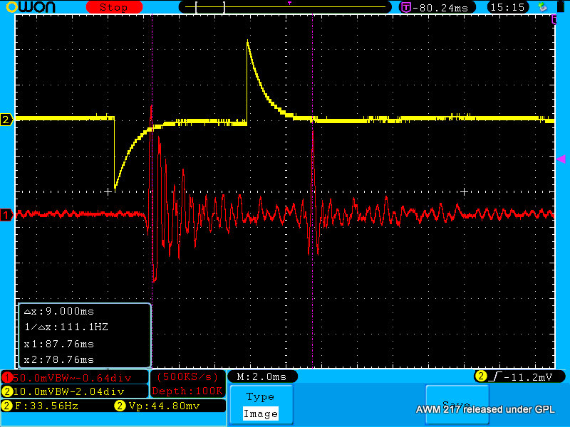
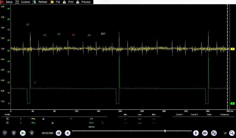
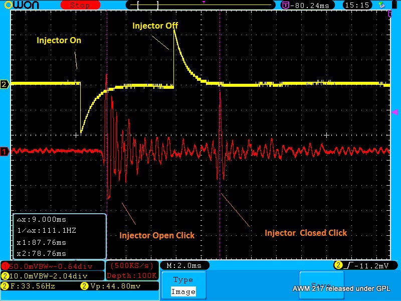
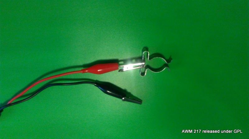
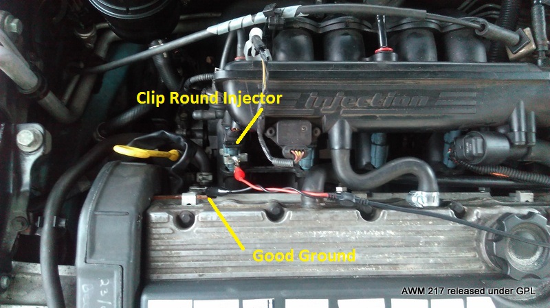
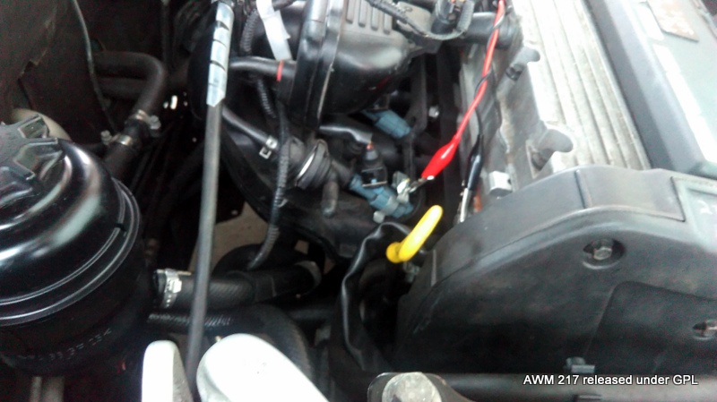
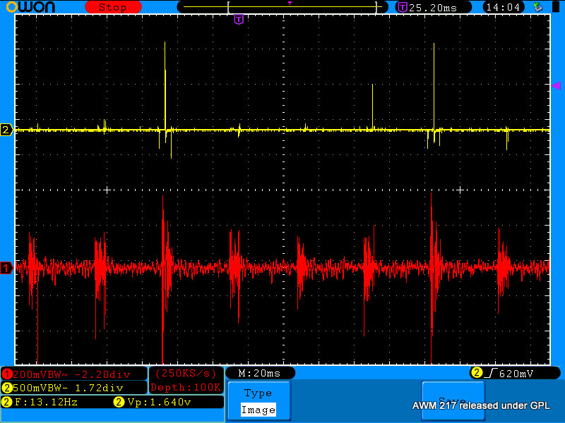
The yellow channel is by capacitive coupling a simple using metal clip round the plastic body of the injector.
Looking at the two signals together is interesting and makes the trace from the electronic stethoscope easier to understand.
" We're trying to plug a hole in the universe, what are you doing ?. "
(Walter Bishop Fringe TV show)
Please Log in or Create an account to join the conversation.
- Tyler
-
Topic Author
- Offline
- Moderator
-
- Full time HACK since 2012
- Posts: 6129
- Thank you received: 1544
Also noticed that the commanded injector on time is around 8ms in this capture, but between the cursors on the stethoscope seems to be closer to 10ms. Great example of how the commanded on time you'll see on the scanner doesn't directly translate to injector open time.
We've been able to see pintle humps in current and voltage waveforms, but this method really illustrates what the pintle is doing when the injector is commanded to open.
Please Log in or Create an account to join the conversation.
- Andy.MacFadyen
-
- Offline
- Moderator
-
- Posts: 3357
- Thank you received: 1037
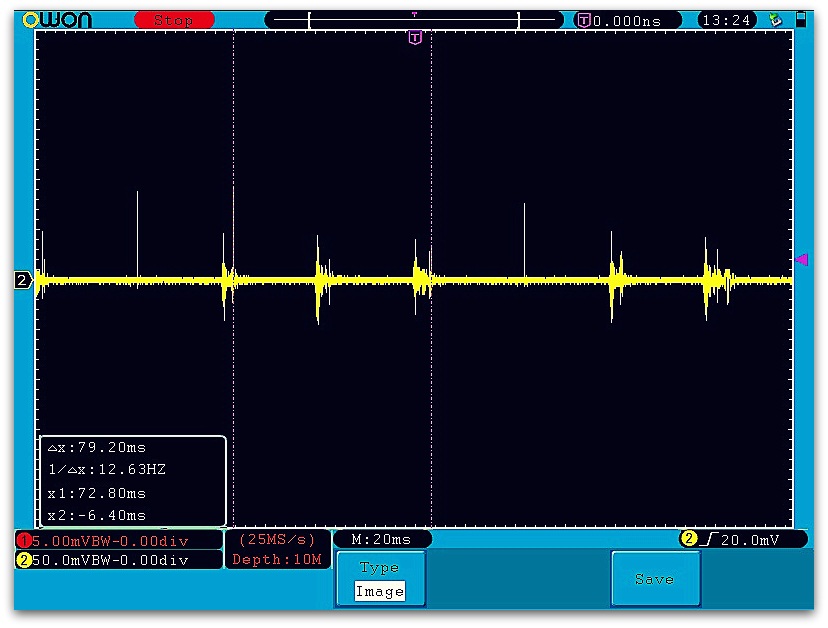
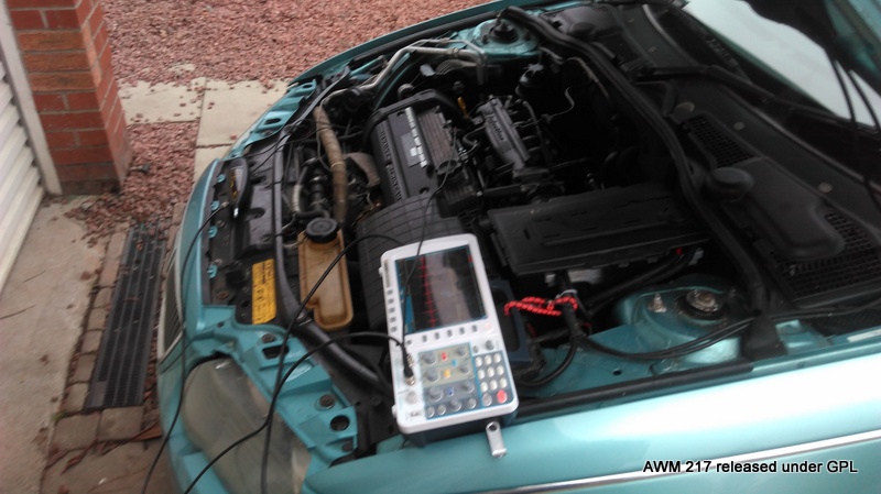
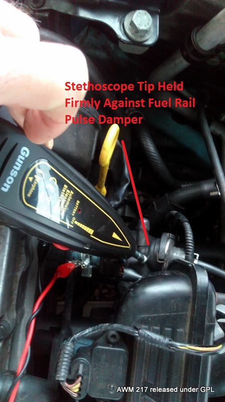
The scope set up that seems to work is;
Horizontal Time base 20mS/div -- screen time = 0.3 seconds.
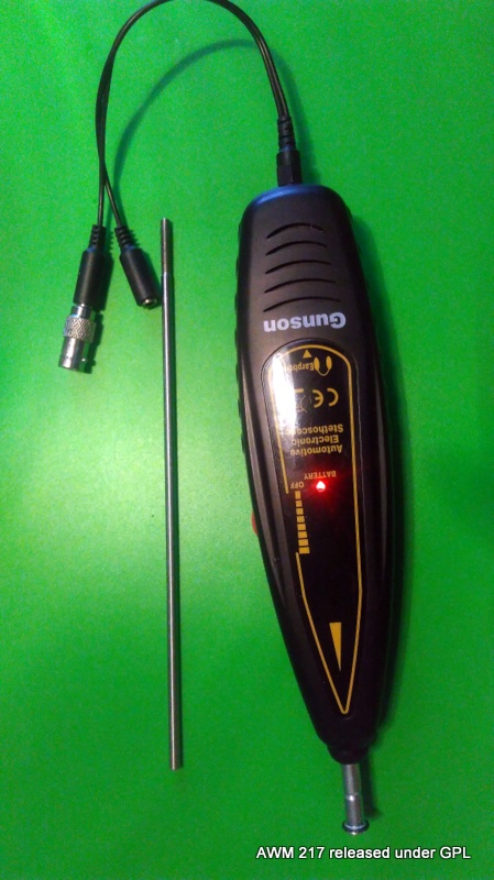
Channel 1 (red) Connected to the Gunson Electronic Stethoscope 200mV/divsion
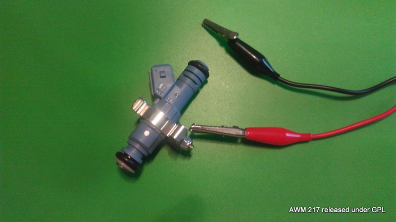
Channel 2 (Yellow) 200mV/div connected indirectly to injector by a capacitive clip this works well with plastic bodied Bosch pencil injector
Trigger from Channel 2 set at 600mV rising.
The Gunson Electronic Stethoscope
Simple t
.jpg)
Tool clip used for capacitive coupling to injector for trigger
" We're trying to plug a hole in the universe, what are you doing ?. "
(Walter Bishop Fringe TV show)
Please Log in or Create an account to join the conversation.
- Andy.MacFadyen
-
- Offline
- Moderator
-
- Posts: 3357
- Thank you received: 1037
" We're trying to plug a hole in the universe, what are you doing ?. "
(Walter Bishop Fringe TV show)
Please Log in or Create an account to join the conversation.