2005 Chrysler Town and Country 3.3 L, signal integrity problem
- EventAlchemy
-
 Topic Author
- Offline
- New Member
-

- Posts: 18
- Thank you received: 11
I have been jumping the gun and thus far purchased two EGR valves. And it basically means I bought two too many.
I have what is called signal integrity problem I think that is the term.
I have P403 and P406, (on 2005 Chrysler town and country 3.3 liters). and it will not go away. The first EGR valve I bought and installed it the check engine light went off for a couple of months and then returned. The new one I bought, well this one the check engine light went away for a day.
So, in a nutshell, I have finally learned enough to do first things first. I jumped/shorted the signal wire to its ground to see if it would change or reset the code. Nothing, absolutely nothing. I have got the same codes. I did it over and over just in case the first time I didn't do a good job.
In fact, it seems the codes are there even after I cleared it with my latest gadget, The Blue Driver.
All other things seem to work, When I applied voltage 12V from the battery to the EGR control valve the signal wire drops to 0.2 volts. Otherwise, it read close to 5 volts when I turn the ignition on and engine not running. The reference pink/yellow reads 5 V.
The rig runs fine so I assume the valve is in the closed position, that much I can conclude.
By the way, I still have the previous EGR valve I bought and I tested it, by supply power to the control wire (#6) and grounded the black wire and the valve opens no problem which I didn't know before how that worked as nobody had told me about it straight forward.
How do I go about fixing signal integrity? Could it mean I have bad sensor ground wire in my case or? Can I ground the sensor wire to the battery/body and if that works, would that mean I have that sensor ground not working or?
Thanks in advance for your help.
And I forgot to check mark the email notification button here. if/when I get a reply.
Please Log in or Create an account to join the conversation.
- jreardon
-

- Offline
- Platinum Member
-

- Posts: 521
- Thank you received: 198

"it read close to 5 volts when I turn the ignition on and engine not running" That would be the p0406, set condition - egr position sensor signal is greater than 4.89V, one trip fault... Normal koeo value should be around 4V - 4.2V
If you have bias voltage on position signal wire, with connector unplugged, check for voltage drop outs on it as you wiggle the pigtail.
South Main Auto has video diagnosing p0406
Please Log in or Create an account to join the conversation.
- EventAlchemy
-
Topic Author
- Offline
- New Member
-
- Posts: 18
- Thank you received: 11
Let me think. So in my rig when the wire harness is unplugged from the valve the computer assumes the valve is open and applies voltage to the signal wire in order to close it and when the signal wire gets the voltage, it completes the circuit inside the valve mechanism and that disconnects the voltage coming from the control wire (#6, dark blk/violet) and that causes the valve to close. The greater the voltage on #6 the more the valve opens etc. ( I assume that is the game of percentage/duty cycle etc).
So I am going to check the ground plugged and unplugged to see what is up with that.
Also, I am wondering how was I able to check the sensor wire having 5 volts with my voltmeter if the minute I test it, the computer would assume that it is grounded and drop the voltage to zero or so? Doesn't voltmeter work the same as if using a test light which implies grounding?
Thanks for everything do you.
Please Log in or Create an account to join the conversation.
- jreardon
-
- Offline
- Platinum Member
-
- Posts: 521
- Thank you received: 198
EventAlchemy wrote: I noticed from your video that the signal wire was reading 5 volts and after you installed the new EGR it was reading around 4.
The PCM sends out the 5V dc bias through a high ohm resistor inside the computer on the signal wire (this is different from the 5v reference voltage circuit) and is usually not seen when everything is in working order. But because the connector was unplugged and there was no ground, the 5V was there and that's how the computer knew to set the p0406. When the connector is plugged in, the weak (weak because it's passing through a high ohm resistor inside computer remember) 5V out of the PCM succumbs to the 4V that is coming out the egr solenoid.
Your voltmeter is not a good path to ground, aka it has high impedance. There is some path to ground but not much. If the 5V went through an even higher ohm resistor, and you used your voltmeter, you would read less than 5 volts as your meter will have some effect/drain on the voltage in the wire.EventAlchemy wrote: Also, I am wondering how was I able to check the sensor wire having 5 volts with my voltmeter if the minute I test it, the computer would assume that it is grounded and drop the voltage to zero or so? Doesn't voltmeter work the same as if using a test light which implies grounding?
Thanks for everything do you.
watch this video to get better understanding on bias voltage, it's for relays but the info is superb:
Please Log in or Create an account to join the conversation.
- EventAlchemy
-
Topic Author
- Offline
- New Member
-
- Posts: 18
- Thank you received: 11
This test was supposed to be in regard to the load side circuit of the relay:
At 16:54 The gentleman emphasizes the importance of jumping the right terminals of the relay connection in the cradle fuse box. It is due to the relay getting flipped over when you place it in the box, it would reflect a different position than seeing them at the relay facing us.
The gentleman shows 87 to be on the bottom right and the 30 pins to be on the top left respectively on the relay itself. At 17:09 he then clearly explains that when you flip the relay over and put it back in its cradle, 87 would be on the bottom left and 30 would be on the top right.
He emphasizes that placing the test and jumping the wrong slots will surely doom and fry the computer. So be very careful to get it right.
At 17:37 you can see where the fellow helper plugs in the pins. Instead of plugging the pins on top right and bottom left he places it on the top left and bottom right. ( Wrong slots or did I have a bad breakfast?)
At 17:53 he asks the helper again if he had placed the pins in the correct slots. I guess so because it wasn't moved and then it was jumped and the sparks were to be expected.
At 25:15 after the wires were fixed at the tank, back at the engine compartment he asks his helper again if he had the pins in the right slots.
It was in the same place back as before, (Top left and bottom right).
What have I missed, because not only the line side of the relay was jumped but the computer also wasn't fried?
Aha, 87 and 30 is the load side. I guess he was basically saying to stay on those pins and not to stay away from it. All is well.
")
Please Log in or Create an account to join the conversation.
- TheTechWhisperer
-

- Offline
- Senior Member
-

- Posts: 55
- Thank you received: 47
The reason I ask, is because those 2 codes are for 2 separately monitored circuits. The p0403 monitors the power wire for the solenoid. The p0406 monitors the signal wire on the potentiometer. It's unlikely that those are both legitimate codes which just set on their own, because they really have little to do with eachother. If they are both completely legit codes, that would really narrow down what you are looking for, such as a crappy/corroded/loose pins in the connector they share, or the harness damaged somewhere nearby.
If you would like further help, please provide the following info:
-KOEO voltages of all 5 wires while back-probing with connector plugged in
-KOEO voltages of all 5 wires with the connector unplugged (on the connector side)
-Do you have access to a non-LED test light?
-Does your scan tool have bi-directional control capability?
"You will always find the greatest fulfillment in life when you are operating in the gifts God gave you"- Dad
National Director of Technical Training & Mechanical Operations - Express Oil Change & Tire Engineers
ASE Master L1 Tech
BMW Master Tech
Ford FACT Advanced Electronics Instructor
Please Log in or Create an account to join the conversation.
- EventAlchemy
-
Topic Author
- Offline
- New Member
-
- Posts: 18
- Thank you received: 11
With the ignition on, car not running I unhooked the harness from the EGR valve and checked the sensor voltage by probing it there (1 terminal) and at the other end hooking my meter at the negative terminal of the battery. I tell you I didn't read a doggone thing. Then I hooked up my meter to the 5 volts (#2 terminal) and the negative battery, something went clicking somewhere which I never heard before. So I didn't like the sound of that and I stopped. I did not want to test the negative (#3 terminal) to the positive side of the battery. I stopped.
I plugged the harness in the EGR valve and I started the van. I read the codes again. What did I find, another extra code appeared P0129. Yea three codes. Grrreeeaat.
So I decided to just delete the codes and after several attempts, something did happen. I managed to erase all the codes, unlike yesterday which I wasn't able to erase the EGR codes whatsoever. Now I managed to clear those plus the new strange barometric mass airflow business. I don't know.
So what did I do next?
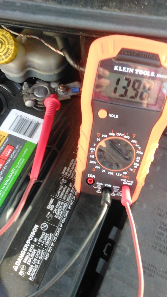
Well, I decided to check the sensor ground and the sensor with the engine running. I hooked up to the sensor ground by taking copper wire and make an "L" out of it, pushed into the harness, hooked up one terminal of my meter into it and the other end of the meter to the positive terminal of the battery. It read almost 14 volts.
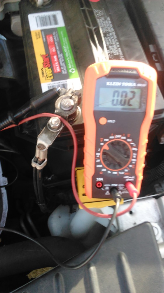
I did the same with the sensor, except I hooked the other end of my meter to the negative side of the battery, I read 0.02 volts.
At present time the van is running fine as before and no codes came back. That is where things are at the present moment.
Please Log in or Create an account to join the conversation.
- EventAlchemy
-
Topic Author
- Offline
- New Member
-
- Posts: 18
- Thank you received: 11
Thank you very much.
I do have a test light. I do not have bidirectional control. I really like to buy one but I don't know which one. All I have is the Blue driver.
Please Log in or Create an account to join the conversation.
- jreardon
-
- Offline
- Platinum Member
-
- Posts: 521
- Thank you received: 198
EventAlchemy wrote: With the ignition on, car not running I unhooked the harness from the EGR valve and checked the sensor voltage by probing it there (1 terminal) and at the other end hooking my meter at the negative terminal of the battery. I tell you I didn't read a doggone thing.
Key on means the computer is powered up, computer powered up means it will be sending out the dc bias voltage on that wire signal wire. The fact you didn't read any voltage tells you there's an open in that wire. This explains why you can't clear the code p0406. As soon as you clear it, cycle the key, the computer immediately knows there's a circuit problem and the code sets again.
You wrote in original post: " I jumped/shorted the signal wire to its ground to see if it would change or reset the code. Nothing, absolutely nothing. I have got the same codes." If the wire was broken, you were grounding a wire that had no physical connection back to the computer, of course it's the same code lol.
Before we get too excited, double check your ground and re-recheck that wire with key on, egr unplugged. Simply put if you were to keep poking holes in the wire all the way back to the computer and you finally find a hole with 5 volts, you'll know that's where your break is.
Sometimes you read 5 sometimes not? You have an intermittent break in the wire or bad contact in terminal.
Please Log in or Create an account to join the conversation.
- TheTechWhisperer
-
- Offline
- Senior Member
-
- Posts: 55
- Thank you received: 47
EventAlchemy wrote: I will check everything on your list tomorrow as you have explained.
Thank you very much.
I do have a test light. I do not have bidirectional control. I really like to buy one but I don't know which one. All I have is the Blue driver.
Alright, and to be crystal clear: When you take those 10 measurements that I asked for, just leave your black lead on battery ground, and you can use that copper L-shaped thing you have with your red lead to back-probe for all the measurements. Remember to take all of these with the KOEO. You can just fill in the blanks that I have right here-
With connector plugged in:
Pin 1:
Pin 2:
Pin 3:
Pin 4:
Pin 6:
With connector unplugged:
Pin 1:
Pin 2:
Pin 3:
Pin 4:
Pin 6:
Don't be offended by me over-simplifying exactly what I want you to do. The info that you initially had posted was really muddy and the terminology/tests you were referencing was confusing. When it comes to electrical diagnostics, clarity and organization is absolutely essential for quick & accurate solutions. It's all about keeping things simple, for as long as the diagnostic path allows. I'm not lecturing you, i'm sharing some tips that will make you more successful.
"You will always find the greatest fulfillment in life when you are operating in the gifts God gave you"- Dad
National Director of Technical Training & Mechanical Operations - Express Oil Change & Tire Engineers
ASE Master L1 Tech
BMW Master Tech
Ford FACT Advanced Electronics Instructor
Please Log in or Create an account to join the conversation.
- VegasJAK
-

- Offline
- Platinum Member
-
- Silencing the Parts Cannon
- Posts: 566
- Thank you received: 140
The fact that you set off a MAP error code maybe related to your problem. The 5v bias is common to the EGR, MAP, AC pressure sensor, cam&crank sensors and throttle position sensor. Why you did not get codes for those sensors suggests to me that the MAP sensor circuit maybe part of the problem.
Unplug the MAP and test the 5v wire on the EGR harness again with the key on engine off... additionally, there is a second sensor wire on the EGR circuit, its the Dk Blu/Vio wire.
"an open mind let's knowledge flow in and wisdom flow out for a man who has neither never listens to those who have both".
Please Log in or Create an account to join the conversation.
- EventAlchemy
-
Topic Author
- Offline
- New Member
-
- Posts: 18
- Thank you received: 11
This is going to be confusing. At least I am. The reading is different. Don't know what to say so here I go.
The ignition on, car not running, harness plugged in.
Pin1. 0.1 volts. Top right ( sensor?)
Pin 2. 5 volts. . Top middle ( supply?)
Pin3. 12 volts when hooked to the positive battery. Top left ( sensor ground?)
Pin4. 12 volts. hooked to the positive terminal of the battery. bottom left under the pin3, ( main ground wire?)
Pin5. empty
Pin6. 0-volt bottom right, under pin1 ( control wire?).
With harness unplugged. Key on. What you see below I have done them at least 3 times if not more.
Pin 1. 0.01 volts when I hooked to the negative terminals of the battery. 12.20v to the positive battery.
Pin2. 5 volts.
Pin3. 6.7V to the positive and 4.55v to the negative battery terminal.
Pin4. 12v to the positive battery. ( bottom left under pin3). 0v to the negative of the battery
Pin5 empty
Pin6. 11.3 v to the positive battery ( bottom right under pin1). 0v to the negative of the battery)
Both two bottom pins read voltages when hooked to positive terminals of the battery. That is not a typo.
Is the rig still running fine? Oh, that third code was back on P0129 just because it wanted to.
I should go and see if I can erase the codes again. I will be back.
Okay, I was able to clear all the codes and the P0129 wasn't part of it. The 203 and 206 only, I cleared them.
So how is that for the confusion. At least it looks to me.
Oh mercy.
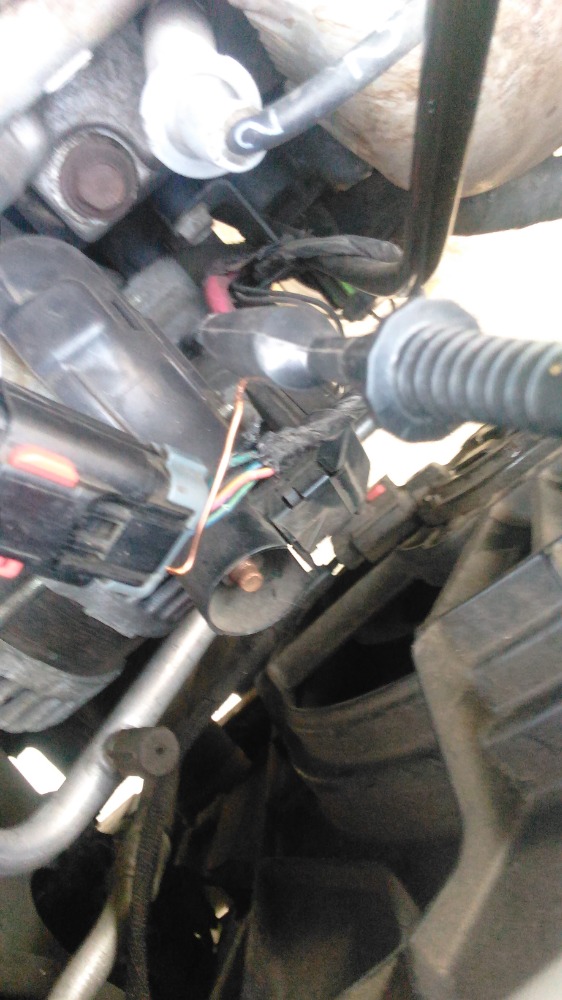
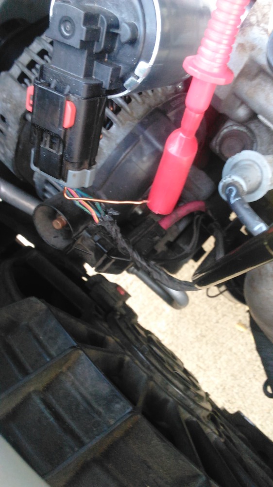
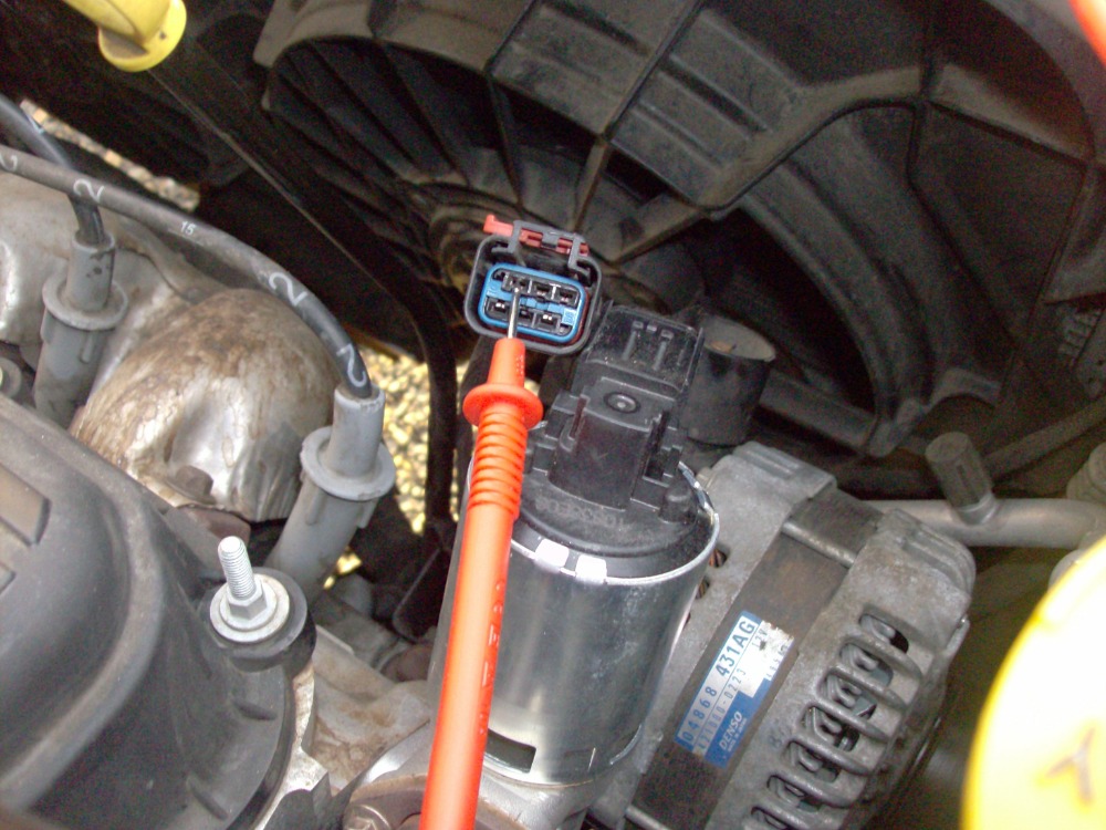
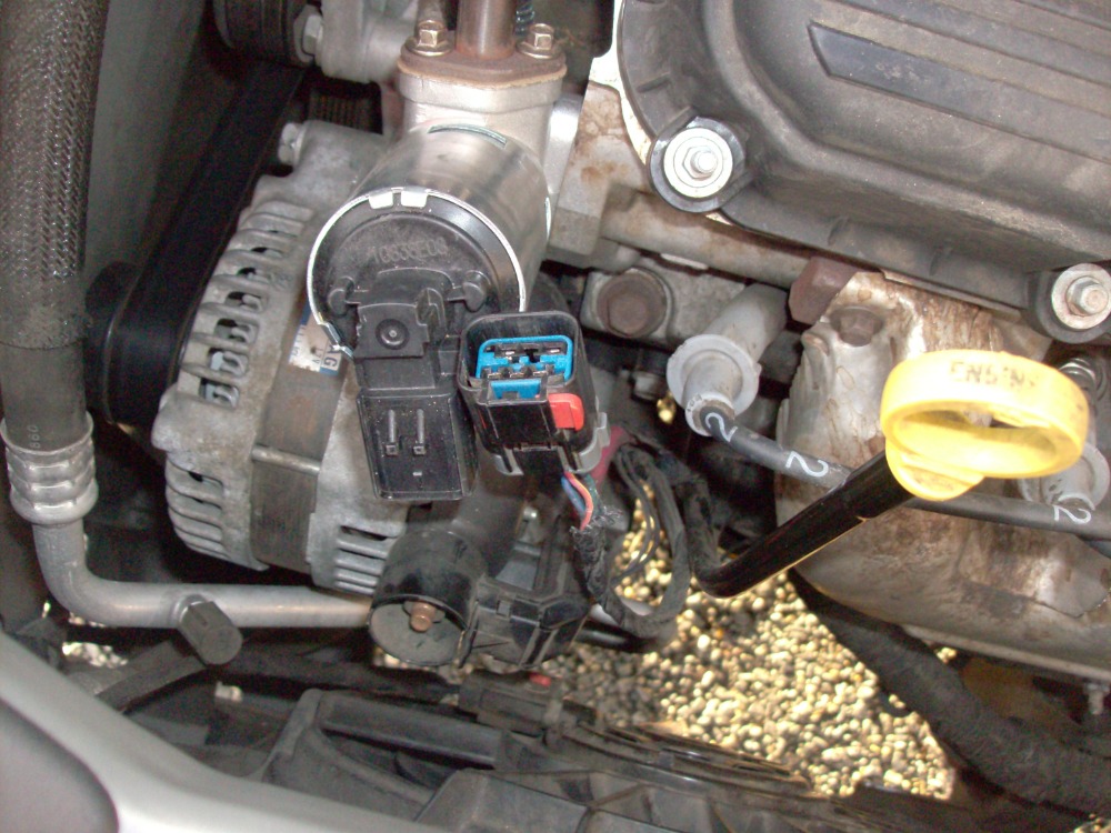
I edited this to include a couple of pictures. I want to make sure I have my pins in the right order. In the picture pointing to pin1 using that probe. So 1 is on the left side of the top row. In the second picture, it would be top right side above that orange locking tab
Please Log in or Create an account to join the conversation.
- TheTechWhisperer
-
- Offline
- Senior Member
-
- Posts: 55
- Thank you received: 47
TheTechWhisperer wrote:
EventAlchemy wrote: I will check everything on your list tomorrow as you have explained.
Thank you very much.
I do have a test light. I do not have bidirectional control. I really like to buy one but I don't know which one. All I have is the Blue driver.
Alright, and to be crystal clear: When you take those 10 measurements that I asked for, just leave your black lead on battery ground, and you can use that copper L-shaped thing you have with your red lead to back-probe for all the measurements. Remember to take all of these with the KOEO. You can just fill in the blanks that I have right here-
With connector plugged in:
Pin 1:
Pin 2:
Pin 3:
Pin 4:
Pin 6:
With connector unplugged:
Pin 1:
Pin 2:
Pin 3:
Pin 4:
Pin 6:
Don't be offended by me over-simplifying exactly what I want you to do. The info that you initially had posted was really muddy and the terminology/tests you were referencing was confusing. When it comes to electrical diagnostics, clarity and organization is absolutely essential for quick & accurate solutions. It's all about keeping things simple, for as long as the diagnostic path allows. I'm not lecturing you, i'm sharing some tips that will make you more successful.
"You will always find the greatest fulfillment in life when you are operating in the gifts God gave you"- Dad
National Director of Technical Training & Mechanical Operations - Express Oil Change & Tire Engineers
ASE Master L1 Tech
BMW Master Tech
Ford FACT Advanced Electronics Instructor
Please Log in or Create an account to join the conversation.
- EventAlchemy
-
Topic Author
- Offline
- New Member
-
- Posts: 18
- Thank you received: 11
The meter black wire at the battery ground at all times.
Key on, wire harness plugged.
Pin1. 0.01v
Pin2. 5V
Pin3. 4.5V
Under Pin1. 0.0v
Under Pin3 . 0.0v
Key on, Harness unplugged.
Pin1. 0.01 v
Pin2. 5v
Piin3. 4.54v
Under pin 1 and pin3 both of them 0.0 volt
I just wanted to say when I unplugged the harness I didn't use the L copper wire. I put the probe directly inside the plug itself. a faster easier and better result I figured.
Please Log in or Create an account to join the conversation.
- EventAlchemy
-
Topic Author
- Offline
- New Member
-
- Posts: 18
- Thank you received: 11
Please Log in or Create an account to join the conversation.
- VegasJAK
-
- Offline
- Platinum Member
-
- Silencing the Parts Cannon
- Posts: 566
- Thank you received: 140
Your original post shows that you put 12v to pin 6 to open the EGR valve and the value at pin 1 went to .2 then went to 5 with KOEO. The 5v is high.
When you do the manual open close of the EGR (power at pin 6)and use a DVOM at pin 1 you will get either fully open .2v or fully closed 3.8v.
Pin 1 voltage plugged in KOEO should be 3.8, unplugged it should be 4.8 or so using the DVOM (5v using a scan tool) as the DVOM draw a little dropping the voltage from 5.
check pins 3 and 4 (ground wires). Use your test light hooked to positive battery and touch each pin. Look for a good strong light at the test light bulb. I'm thinking one is going to be dim... suggesting a short.
"an open mind let's knowledge flow in and wisdom flow out for a man who has neither never listens to those who have both".
Please Log in or Create an account to join the conversation.
- jreardon
-
- Offline
- Platinum Member
-
- Posts: 521
- Thank you received: 198
Anyway...EventAlchemy when you pointed out pin 1 in the photo using your meter lead, that's actually pin 3 according to Chrysler. The voltages you were reporting didn't quite match up with the expected pin numbering in the mitchell diagram. So in the interest of everyone being on the same page, just swap the pin 1 voltage with the pin 3 voltage from EventAlchemy's post
")

Please Log in or Create an account to join the conversation.
- VegasJAK
-
- Offline
- Platinum Member
-
- Silencing the Parts Cannon
- Posts: 566
- Thank you received: 140
I have heard that aftermarket EGR's for Chrysler are not reliable and that you should use an OEM.
With KOEO and harness unplugged, jump pin1 and pin 3 this should set off a low voltage code... if it does your wiring is good.
"an open mind let's knowledge flow in and wisdom flow out for a man who has neither never listens to those who have both".
Please Log in or Create an account to join the conversation.
- EventAlchemy
-
Topic Author
- Offline
- New Member
-
- Posts: 18
- Thank you received: 11
As I was walking with my dogs today, it suddenly came to me that I have failed to mention here that I am color blind. And besides that I had a feeling I never had my pin numbers correct. I certainly had it all backward. I somehow did manage to use enough savvy to take a picture and sent it just to put it out there what I thought was pin1. I had this funny feeling that it was in fact probably pin3.
The correct sequence of pins:
What I am pointing at with my probe is pin 3 ( sensor ground). Pin1 is on the first right. Got it.
Pin2, that one naturally can not get swapped ( only because the star of the show is in the middle. It can't go anywhere else
)Pin4 (main ground), that is under the pin1.
The pin 6 ( control wire) is under the pin 3.
All this time I have had my pins scattered all over the planet.
(By the way, I had neglected totally and should come clear here. When I had mentioned that I tested the EGR valve; and connected pin 6 and pin 4 to open. I was really testing the one I had taken out, the previous one. Yea I was testing it on the bench. I was doing it because I had this sudden realization that if I have my understanding correct. Those two pins are what opens and close the valve after all. I simply found out, that I was right in that even though I had the pins, backward. I guess the EGR valve didn't care. That is what that was about.
).So I am going to follow what you have stated and see what is going on.
Please Log in or Create an account to join the conversation.
- EventAlchemy
-
Topic Author
- Offline
- New Member
-
- Posts: 18
- Thank you received: 11
1. With the engine running, when I put 12V from the battery to terminal 6 the rig would die in before I even had any chance to see the voltage on pin1 as how to how much or quickly and to what lower voltage it would reach. Sensor wire didn't have a chance to stabilize in any meaningful way.
2. Both ground terminals pin3 and pin4 were nice and bright on the test light and 14.20V on the meter.
3. The sensor is at 4.54V plugged or unplugged either way.
I did something stupid but thank goodness it didn't cause any serious problem.
I read that you said to put power to pin6 with the engine running. That is one thing. But then the stupid inside of me put power to pin6 when the engine wasn't running. I could tell something didn't feel right.
In a bit, I was checking the sensor 1 and it was reading fluctuating 4.5 to 7.50 volts only to realize that it was worse, with the ignition switch off, that is.
Well, I checked the codes and it had thrown P0688.
Long story short, the code has disappeared and the rig runs fine.
End result I am left with only P0406 with 4.54V, regardless if it is plugged or not or if the engine running. For some reason, that number seems rather repetitive throughout. The little guy is stuck on volt and can't get out of it. while everything else seems normal even though they all got jerked around by the novice here. There is no justice.
Follow up:
I don't remember if I have done this before. I went ahead and checked power (pin2) to sensor ground (pin3) and also the main ground (pin4). They read 4.9V, with the ignition on and plugged in. I also checked the sensor to main ground pin4, it is at you guessed it 4.54V.
I did not want to touch pin1 to pin3 just because. I don't want to set any funny codes.
I just realized I can do freeze frame with Bluedriver. Maybe I will take the rig for a drive with Bluedriver monitoring if that would mean more?
Please Log in or Create an account to join the conversation.