I have a question about Section 10 circuit integrity testing
- XsleepercellX
-
 Topic Author
- Offline
- Senior Member
-

Less
More
- Posts: 59
- Thank you received: 7
5 years 4 months ago #47227
by XsleepercellX
I have a question about Section 10 circuit integrity testing was created by XsleepercellX
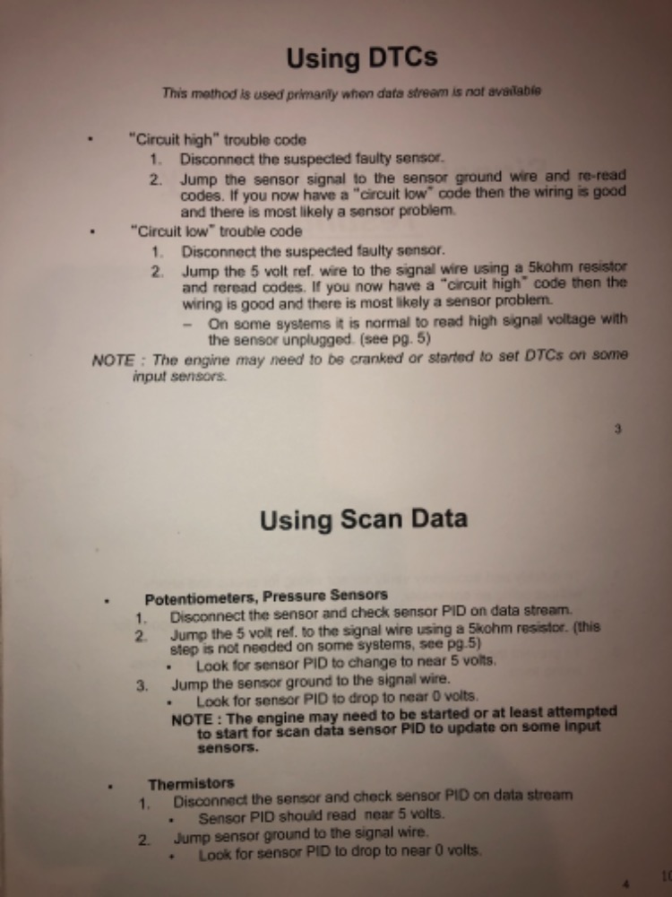
Section 10 page 10-2 Using DTCs, •circuit high trouble codes
Its saying to disconnect the sensor signal wire and jump it to the sensor ground, then if you have a circuit low code it says to jump the 5 volt ref wire to the signal wire... can anyone elaborate on this for me? I’m fairly new to engine performance diagnostics and trying to do it right which is why I’m here. My concern is which sensors can I jump like this and be confident I’m not going to damage a computer? I attached a picture of the page I’m inquiring about... thanks for any help in advance!
Its saying to disconnect the sensor signal wire and jump it to the sensor ground, then if you have a circuit low code it says to jump the 5 volt ref wire to the signal wire... can anyone elaborate on this for me? I’m fairly new to engine performance diagnostics and trying to do it right which is why I’m here. My concern is which sensors can I jump like this and be confident I’m not going to damage a computer? I attached a picture of the page I’m inquiring about... thanks for any help in advance!
Please Log in or Create an account to join the conversation.
- Chad
-

- Offline
- Moderator
-

- I am not a parts changer.
Less
More
- Posts: 2199
- Thank you received: 741
5 years 4 months ago - 5 years 4 months ago #47240
by Chad
"Knowledge is a weapon. Arm yourself, well, before going to do battle."
"Understanding a question is half an answer."
I have learned more by being wrong, than I have by being right.")
Replied by Chad on topic I have a question about Section 10 circuit integrity testing
The computer sends out a bias voltage on the signal, or control wire. This voltage varies from system to system. In this example, I will use 5 volts.
The computer monitors the voltage on the signal, or control wire. Depending on circuit design, the component/sensor will pull this bias voltage up, or down, when it is connected. For example, a ground-side switched O2 heater control circuit. A bias voltage can be used on the control wire. The O2 heater power wire has Battery voltage all the time. The computer provides a ground, on the control, to turn it on. When the sensor is connected, but the heater is not turned on, the 5 volt bias on the control wire will be "pulled up" to 12 volts. The computer will "see" the 12 volt battery voltage on the control wire, coming through the heater element. The computer expects to see this. When you unplug the sensor, the battery voltage from the heater power can not travel through the heater element, the 5 volt bias is not "pulled up". The computer no longer sees battery voltage, but now sees the 5 volt bias. This tells the computer that the circuit is OPEN. If the control wire was shorted to ground, the 5 volt bias would be "pulled down" to ground. When the computer sees less than what it expects to see, then the Heater Control circuit is LOW.
In short, the PCM sees voltage that is Higher than, Lower than, or equal to the bias voltage. You should be able to manipulate these voltages with a test-light connected to either power, or ground (the test-light should not illuminate). If you CAN manipulate them as you would expect, then this gives you confidence of circuit integrity. If you CAN'T manipulate them, and the test light illuminates, then you likely have a true short to power, or ground.
"Knowledge is a weapon. Arm yourself, well, before going to do battle."
"Understanding a question is half an answer."
I have learned more by being wrong, than I have by being right.
Last edit: 5 years 4 months ago by Chad.
Please Log in or Create an account to join the conversation.
- Chad
-
- Offline
- Moderator
-
- I am not a parts changer.
Less
More
- Posts: 2199
- Thank you received: 741
5 years 4 months ago - 5 years 4 months ago #47241
by Chad
"Knowledge is a weapon. Arm yourself, well, before going to do battle."
"Understanding a question is half an answer."
I have learned more by being wrong, than I have by being right.
Replied by Chad on topic I have a question about Section 10 circuit integrity testing
Here, is a video showing ScannerDanner manipulating, and explaining, the bias voltage on the power-side switched Fuel pump relay.
"Knowledge is a weapon. Arm yourself, well, before going to do battle."
"Understanding a question is half an answer."
I have learned more by being wrong, than I have by being right.
Last edit: 5 years 4 months ago by Chad.
The following user(s) said Thank You: Noah
Please Log in or Create an account to join the conversation.
Time to create page: 0.235 seconds