Pull-up and Pull-down circuit discrepancies in videos.
- StingRayZ
-
 Topic Author
- Offline
- New Member
-

Less
More
- Posts: 2
- Thank you received: 2
5 years 8 months ago - 5 years 8 months ago #43872
by StingRayZ
Pull-up and Pull-down circuit discrepancies in videos. was created by StingRayZ
Hello, been watching a couple of videos in the premium section and noticing that pull-up and pull-down circuits are being identified wrong. Namely in this video,
switch input identification and bypass testing live example gm acadia
. Where as the circuit being discussed is actually a pull-down circuit but is continually called a pull-up circuit. The pull-up resistor is keeps signal voltage high where as without it there would be a floating signal voltage. Signal voltage is high until the switch is closed and then signal voltages goes low. I think this is where alot of people get confused because with a switch closed and then the voltage is pulled low, it is then called a pull-down circuit where that is not the case. Likewise with the pull-down resistor the signal voltage is kept low. When a switch in the circuit is open signal voltage is low and when the switch is closed signal voltage goes high which for that reason people tend to call the circuit a pull up circuit, which again is not correct. Circuits are inverse logic.
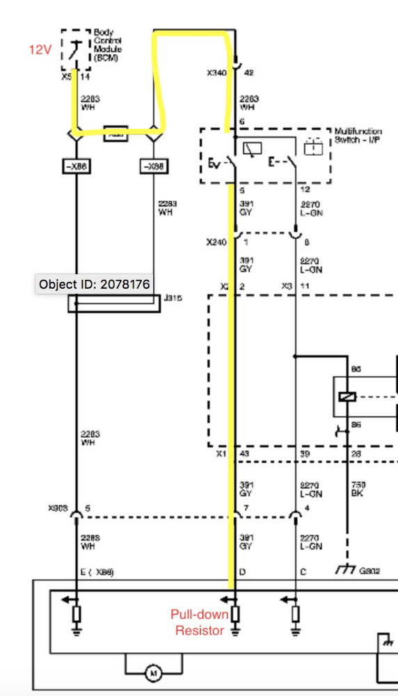
please see attachments for schematic of circuit being discussed in video.
Would love to see Paul respond and have a discussion about this.
please see attachments for schematic of circuit being discussed in video.
Would love to see Paul respond and have a discussion about this.
Last edit: 5 years 8 months ago by StingRayZ.
The following user(s) said Thank You: Noah
Please Log in or Create an account to join the conversation.
- StingRayZ
-
Topic Author
- Offline
- New Member
-
Less
More
- Posts: 2
- Thank you received: 2
5 years 8 months ago #43889
by StingRayZ
Replied by StingRayZ on topic Pull-up and Pull-down circuit discrepancies in videos.
Figured since no responses I would add a quick video if interested.
Pull-up and Pull-down Resistors
Pull-up and Pull-down Resistors
The following user(s) said Thank You: Noah
Please Log in or Create an account to join the conversation.
- Noah
-

- Offline
- Moderator
-

Less
More
- Posts: 5051
- Thank you received: 1125
5 years 8 months ago - 5 years 8 months ago #43893
by Noah
Replied by Noah on topic Pull-up and Pull-down circuit discrepancies in videos.
Crikey, must be different down unda!
Anticlockwise drains and Summer in December and what not.
Anticlockwise drains and Summer in December and what not.
Last edit: 5 years 8 months ago by Noah.
Please Log in or Create an account to join the conversation.
- Noah
-
- Offline
- Moderator
-
Less
More
- Posts: 5051
- Thank you received: 1125
5 years 8 months ago - 5 years 8 months ago #43894
by Noah
Replied by Noah on topic Pull-up and Pull-down circuit discrepancies in videos.
Please know I'm just playing with you.
In all seriousness and with all due respect, it sounds counterintuitive and directly contradicts what is being taught here, so I'm sure you must have expected it to not be a popular position.
But, in the interest of keeping an open mind and expanding my own knowledge, I'll spend some time on the Google machine.
Is there another source you could post as reference?
EDIT:
I think I see both sides of the coin now.
In the example you provided,(and, to your credit, many others), emphasis is on the state of the resistor. I assume that is how the engineering side of the world would quantify the internal construction of the PCM.
For troubleshooting purposes, we've been defining pull up and pull down switch inputs by the state of the switch.
Paul (Scanner Danner) is not alone in this description.
www.google.com/amp/s/autosystempro.com/switch-inputs/amp/
It is an interesting point, thank you for bringing it to the attention of the community!
Last edit: 5 years 8 months ago by Noah.
Please Log in or Create an account to join the conversation.
- Flatrater
-
- Offline
- Senior Member
-

Less
More
- Posts: 48
- Thank you received: 18
5 years 8 months ago #43900
by Flatrater
Replied by Flatrater on topic Pull-up and Pull-down circuit discrepancies in videos.
Not sure I'm following exactly what the disagreement is and I didn't watch the video...
That was a pull-down resistor. There is more than one type of digital logic that could be used, but at the end of the day the input will "float" if it is not pulled down when the input is open. When the input is closed, the pull-down resistor selection will have little effect on the input voltage.
Its not about the resistor, its about giving the logic (op amp, etc.) a specific state so that it doesn't float all over the place.
PCM (etc.) internal schematics are ALWAYS grossly simplified. Unfortunately, wrong as well at times.
Please Log in or Create an account to join the conversation.
- Tutti57
-

- Offline
- Platinum Member
-

Less
More
- Posts: 1098
- Thank you received: 253
5 years 8 months ago #44046
by Tutti57
Replied by Tutti57 on topic Re:Pull-up and Pull-down circuit discrepancies in videos.
The way I understand the way Paul teaches it is how Noah explained. Voltage difference with switch change. I believe it's one of Paul's lectures where he says he doesn't know if it's an actual term, but just what he calls it because it's what you would see with your measurements outside of the module.
Nissan Technician
Nissan Technician
The following user(s) said Thank You: Noah
Please Log in or Create an account to join the conversation.
- Flatrater
-
- Offline
- Senior Member
-
Less
More
- Posts: 48
- Thank you received: 18
5 years 8 months ago #44060
by Flatrater
Replied by Flatrater on topic Re:Pull-up and Pull-down circuit discrepancies in videos.
This is an interesting thread. Hope you don't mind me butting in a little more.
I am not sure how it was taught, but within the electronics world, there aren't multiple choices. One is correct and the other is not")
To diagnose vehicle faults, one typically only needs to understand the function. But to understand circuit operation at any depth, one needs more than that.
I have seen a number of instructors point to voltage divider sensor circuits (ex 3-wire sensor) as pull-up or pull-down circuits. They are neither. However... on the signal wire it is common to have a pull-up or pull-down function.
In those cases, the input is being sampled by digital logic circuits that must have something to work with otherwise the input will float.
I'm purposefully using the vague term "digital logic" because logic circuits can be created multiple ways.
OEs vary a great deal in their training, but I remember GM training bringing attention to this in their 1994 OBD2 training material. Technicians were making incorrect assumptions of testing PCM driver and sensor circuits based on what they had learned to do with older technology.
I am not sure how it was taught, but within the electronics world, there aren't multiple choices. One is correct and the other is not
To diagnose vehicle faults, one typically only needs to understand the function. But to understand circuit operation at any depth, one needs more than that.
I have seen a number of instructors point to voltage divider sensor circuits (ex 3-wire sensor) as pull-up or pull-down circuits. They are neither. However... on the signal wire it is common to have a pull-up or pull-down function.
In those cases, the input is being sampled by digital logic circuits that must have something to work with otherwise the input will float.
I'm purposefully using the vague term "digital logic" because logic circuits can be created multiple ways.
OEs vary a great deal in their training, but I remember GM training bringing attention to this in their 1994 OBD2 training material. Technicians were making incorrect assumptions of testing PCM driver and sensor circuits based on what they had learned to do with older technology.
Please Log in or Create an account to join the conversation.
- Ohmega Diagnostics
-
- Offline
- New Member
-
Less
More
- Posts: 8
- Thank you received: 3
5 years 8 months ago #44089
by Ohmega Diagnostics
Replied by Ohmega Diagnostics on topic Pull-up and Pull-down circuit discrepancies in videos.
Hi, there is a lot to learn from the video not everyone here is a circuit designer or electronics engineer. I personally like the quick tests performed to rule out circuit fault or bad switch by providing a signal with the test light (I don't personally own one ). Also for demonstrating how to test the switch without a wiring diagram and what to look for just using the multimeter.
Paul, thanks for sharing your techniques and quick test to arrive at a conclusion to make a call on replacing a defective part.
Paul, thanks for sharing your techniques and quick test to arrive at a conclusion to make a call on replacing a defective part.
The following user(s) said Thank You: Tutti57, spiercev
Please Log in or Create an account to join the conversation.
- Flatrater
-
- Offline
- Senior Member
-
Less
More
- Posts: 48
- Thank you received: 18
5 years 8 months ago #44095
by Flatrater
Replied by Flatrater on topic Pull-up and Pull-down circuit discrepancies in videos.
Interesting... I'm not an electronics engineer and it has been 30+ years since I pursued a degree in electronics with night classes at a local JC. I found it hugely helpful in troubleshooting problems. I also knew it would be key in the future.
Vehicle electronics have changed since then and will continue to do so. Learning "quick tests" without knowing the caveats creates problems down the road. That said, I teach them as well. So please don't misunderstand what I'm trying to say.
For example, when vehicles began using active wheel speed sensors, it stumbled a number of technicians because they learned quick tests that no longer applied. Many educators taught that sensors with digital outputs needed 3 wires and that was a way of identifying what the output would look like. Not true.
Driver circuits, sensors, etc. have evolved considerably over the years. We have to be careful of what we assume. Another example might be, O2 sensors. Some have no bias, some have 450mv, some have 5v, some have 1.9v etc. GM alone has at least three variations.
In the 80s we had discrete drivers that had no current protection, later there were quad drivers with current protection, then there were quad drivers with current protection and fault identification. Then there were 10x drivers, smart drivers, etc...
I was a driveability flatrate tech for 35 years, I totally get the "quick test" thing as I've done it myself a gazillion times. But... it was with the caveats in mind. I knew the risks of what I was assuming. Sometimes they stung me and much more often they worked.
Here's something... I had a late 90s GM truck that was setting an IC circuit fault. The engine ran great and I scoped the signal that the PCM was flagging as faulty. It had a perfect waveform. I replaced the module with a new part. The waveform was no different than before but the code went away. So what was going on?
The PCM was monitoring the current, not the voltage on the signal. The faulty module was pulling half the current it was supposed to. Actually, it was monitoring the voltage, but as a function of the circuit current across an internal resistor.
The following user(s) said Thank You: spiercev
Please Log in or Create an account to join the conversation.
- andyhilton27
-
- Offline
- New Member
-
Less
More
- Posts: 1
- Thank you received: 0
5 years 7 months ago - 5 years 7 months ago #44387
by andyhilton27
Replied by andyhilton27 on topic Pull-up and Pull-down circuit discrepancies in videos.
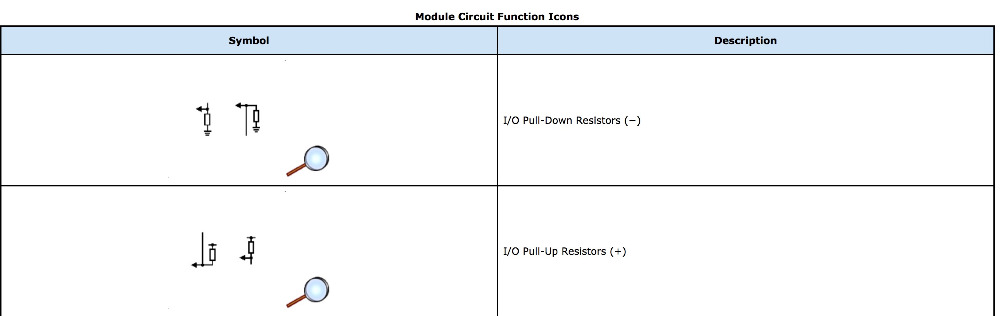
A pull-up resistor connects unused input pins (AND and NAND gates) to the dc supply voltage, (Vcc) to keep the given input HIGH. A pull-down resistor connects unused input pins (OR and NOR gates) to ground, (0V) to keep the given input LOW.
Last edit: 5 years 7 months ago by andyhilton27.
Please Log in or Create an account to join the conversation.
- Flatrater
-
- Offline
- Senior Member
-
Less
More
- Posts: 48
- Thank you received: 18
5 years 7 months ago #44409
by Flatrater
Replied by Flatrater on topic Pull-up and Pull-down circuit discrepancies in videos.
I believe what you mean by "unused" is that the input is open when is should not be. Is that what you meant?
Please Log in or Create an account to join the conversation.
Time to create page: 0.259 seconds