Honda A/F Ratio & Assoc Components Diagnostics
- John Clark
-
 Topic Author
- Offline
- Premium Member
-

- Posts: 136
- Thank you received: 46
Based on the miles on them, I went ahead and just replaced both upstream A/F sensors (they were original) and now total fuel trims are at around +3-4% total, so I'm fixed and happy. However, that's where my inquiring mind has some questions.
When I looked at live data for the A/F sensors before replacing I couldn't see anything wrong with them (using info from your Lexus A/F ratio videos from 2013) but they were obviously causing the computer to add fuel when it didn't need it after all those miles. 10K ago I had my first oil analysis come back with a glowing result but they mentioned just a trace of fuel in the oil. The trace was so small that while Blackstone Labs noted it, they weren't concerned about it. Now I see it was probably another clue to the computer adding fuel when it didn't need to.
After replacement of the A/F ratio sensors, my average fuel economy jumped up 2-3 mpg in the first tank of gas after replacement with no real change in driving conditions. I'm probably going to change the oil and then have the oil analyzed again at the next oil change after that and see if that trace of fuel is gone from the analysis.
My question is this. Do you have any other videos or information that deal with this? I'm curious how I could have known for sure, before replacing, that my A/F sensors were getting worn, dirty or lazy even though there were no codes being set (aside from having 165K miles on them.) The A/F sensors are a bit pricey and it was a little risky spending the money for two new ones when I wasn't 100% positive they would solve my problem, though I was fairly sure. Also, I haven't seen any videos on how to check cat efficiency on A/F vehicles. On regular O2 cars it's pretty simple but how is it done on A/F vehicles?
I'd love to see some more videos on A/F sensor and associated component diagnostics.
Thanks!
John
Please Log in or Create an account to join the conversation.
- Posts: 4443
- Thank you received: 968
I don't know a great deal when it comes to wideband sensor diagnostics. Tyler has put together a great thread describing some of the more common variations of these systems here: Wideband AFR Sensor Diagnostics
There's also some contributions from other members in there. Definitely worth the read.
"Ground cannot be checked with a 10mm socket"
Please Log in or Create an account to join the conversation.
- cheryl hartkorn
-
- Offline
- Platinum Member
-

- Posts: 692
- Thank you received: 130
Please Log in or Create an account to join the conversation.
About your Odyssey... I can't say I can think of a way you could have been more sure about your sensor replacement call.
 Obviously, the PCM was happy enough with their performance (no codes), but there was clearly an improvement afterwards. I've seen A/F sensors stick full rich or full lean, but never one that simply became... skewed? That's the best word I can think of to describe it. :lol:
It may be that, like conventional O2 sensors, that the sensor element degrades over time. Not in it's response time, but in it's stoichiometric reference. I wonder what a five gas analyzer might have told you? If the mixture truly was 10% richer than it should've been, then I'd think it'd show elevated CO readings. Just speculating.
About catalyst testing with A/F sensors, that I can answer! :lol: It's far more straightforward than you might think. The old strategy of watching for the downstream sensor signal switching during a steady cruise still broadly applies. Even though the signal from an A/F sensor doesn't switch lean and rich, it's job is still to keep the mixture at stoichiometric (except for those times the PCM commands different mixtures, but that's a separate issue). Therefore, if the catalyst is dead, then the downstream O2 will reflect the mixture hovering around 14.7/1.
Here's a couple examples. This one is a capture I took off an '06 Tacoma with a stored P0430 B2 cat code. The A/F sensors are at the bottom, and the O2's directly above:
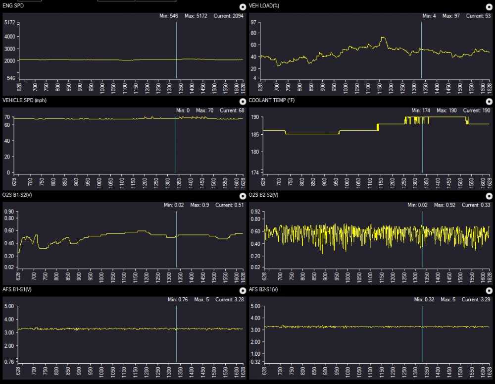
The B1 downstream O2 is very smooth, as it should be, but B2 is all over the place! As another example, here's one of the PCM's active catalyst tests. Watch the PCM intentionally jam the mixture rich and lean rapidly (as seen in the A/F sensors), and look how the downstream sensors respond:
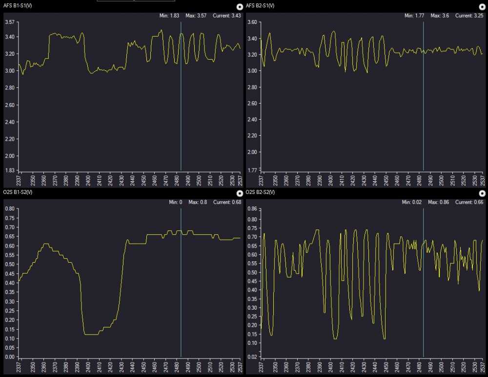
The B1 downstream barely noticed that anything happened, but the B2 downstream followed the mixture changes step for step. Stick a fork in it, 'cause it's done.
")
Please Log in or Create an account to join the conversation.
- John Clark
-
Topic Author
- Offline
- Premium Member
-
- Posts: 136
- Thank you received: 46
cheryl hartkorn wrote: on Hondas you have this thing in data called pump current positive readings indicate a lean condition and negative numbers indicate a rich condition. it will be displayed in milliamps on the scanner. also you should have a piece of information called "af fb" that is there term of fuel trim 1.00 is equal to 0 like in global. example reading of 0.64 would indicate a 36% rich condition or 1.34 would be 34% lean. they also have dual cell air fuel ratio sensors. how many wires did your sensors have? I don't have a wiring diagram for the van
I figured out the OEM style of fuel trim pretty easily and that's how I got the fuel trim numbers I posted about. I don't recall the "pump current" label but I do recall seeing a current reading which pretty much read zero all the time but quickly fluctuated up and down but stayed around zero. If I understand correctly, that's what they're supposed to do.
For wiring diagrams I have the factory service manual but have used www.bbbind.com/free_tsb.html for quite some time when I needed them for other vehicles. I think I saw that site listed here in the forums.
Here's the diagram for my Ody. See page 6:
www.revbase.com/BBBMotor/Wd/DownloadPdf?id=157753
Please Log in or Create an account to join the conversation.
- John Clark
-
Topic Author
- Offline
- Premium Member
-
- Posts: 136
- Thank you received: 46
Tyler wrote: Hey John, welcome to the forums! I moved this to the Diagnostic tools & techniques section, FYI.
About your Odyssey... I can't say I can think of a way you could have been more sure about your sensor replacement call.
It may be that, like conventional O2 sensors, that the sensor element degrades over time. Not in it's response time, but in it's stoichiometric reference. I wonder what a five gas analyzer might have told you? If the mixture truly was 10% richer than it should've been, then I'd think it'd show elevated CO readings. Just speculating.
About catalyst testing with A/F sensors, that I can answer! :lol: It's far more straightforward than you might think. The old strategy of watching for the downstream sensor signal switching during a steady cruise still broadly applies. Even though the signal from an A/F sensor doesn't switch lean and rich, it's job is still to keep the mixture at stoichiometric (except for those times the PCM commands different mixtures, but that's a separate issue). Therefore, if the catalyst is dead, then the downstream O2 will reflect the mixture hovering around 14.7/1.
Here's a couple examples. This one is a capture I took off an '06 Tacoma with a stored P0430 B2 cat code. The A/F sensors are at the bottom, and the O2's directly above:
The B1 downstream O2 is very smooth, as it should be, but B2 is all over the place! As another example, here's one of the PCM's active catalyst tests. Watch the PCM intentionally jam the mixture rich and lean rapidly (as seen in the A/F sensors), and look how the downstream sensors respond:
The B1 downstream barely noticed that anything happened, but the B2 downstream followed the mixture changes step for step. Stick a fork in it, 'cause it's done.
No problem on the thread move. However, I was hoping to get the word to Paul that it would be great to see some wideband A/F diagnostic videos (thus why I posted in the case study section.) The only ones he has on his free channel are the two Lexus videos from 2013. I follow all the top diagnostic YT channels (SMA, MotoYam82, SD, Shroedinger's Box, etc.) and nobody has any really good case studies of wideband sensor vehicle diagnostics. Maybe they're still just too new or maybe I'm just not the only one that doesn't fully understand them.
Thanks for the scan data examples. It verifies what I thought I'd see in the case of a bad cat on a wideband system. Am I correct in thinking that I'm basically looking for similar switching on the downstream sensor? That's how it appears in your scan data shots. I changed my A/F sensors just so I wouldn't get any personal experience on it! I follow the Odyclub.com and Piloteers.com forums fairly regularly and I see people often get P0420/0430 codes out of the blue (with relatively low miles, i.e. 120K, etc.) and often wonder how that happens without any other codes beforehand. Is it from oil burning, poor quality fuel, or is it from these wideband sensors pushing up the fuel trims, as in my case, and the excess fuel deteriorating the cats. A +20% fuel trim seems high to me but Honda decided not to set a code until at least 25%. I'd just hate to learn about a bad O2 by getting a P0420/0430 first.
Please Log in or Create an account to join the conversation.
- CurrentDraw
-
- Offline
- Junior Member
-

- Posts: 37
- Thank you received: 27
Once exhaust sample enters the diffusion chamber the process begins.
1. VS (voltage sensing) cell creates a voltage based on exhaust sample to signal if mixture is simply RICH or LEAN.
2. PCM sends voltage to the IP (ion pumping) cell to either pump oxygen in or out of chamber based on voltage applied.
3. Current generated (PCM Input) from the applied voltage in diffusion chamber is used to calculate the exact A/F ratio.
Another unique feature of this sensor is that both the AF sensor and secondary oxygen sensors are used to modify the fuel trim. I'm sure other manufacturers are also using this method, please chime in if you know.
Generally we monitor 3 parameters using the HDS live data if we suspect a faulty sensor;
1. AF sensor in mA
2. AF FB CMD (feedback command)
3. AF FB (feedback actual)
Being at the dealer I have the luxury of comparing the readings to another vehicle although the foreman has a quick lookup chart/table to compare the readings. Last but not least we can always try Honda's infamous method of swapping a "known good" part from another vehicle and see if the fuel trims get back to normal
") .
.If I remember correctly from training the propane test will not work with the Ion pumping sensor. I haven't tested this myself to confirm if true or not.
Please Log in or Create an account to join the conversation.
- Andy.MacFadyen
-

- Offline
- Moderator
-

- Posts: 3353
- Thank you received: 1031
If anybody here can remember high school chemistry it was called chromatogtraphy.
Although there are various kits such as "Oil Spy" "EngineCheckup" all you need is a small sheet of white card and the information on what to look for in the results.
link to EngineCheckup site
link to Oil Spy site
" We're trying to plug a hole in the universe, what are you doing ?. "
(Walter Bishop Fringe TV show)
Please Log in or Create an account to join the conversation.
- John Clark
-
Topic Author
- Offline
- Premium Member
-
- Posts: 136
- Thank you received: 46
CurrentDraw wrote: The oxygen Ion pumping AF sensor on your Honda uses a 3 step process to analyze the exhaust sample in the diffusion chamber in order to figure out the exact A/F ratio. It is a bit different than the Critical Current AF sensor which Honda uses.
Once exhaust sample enters the diffusion chamber the process begins.
1. VS (voltage sensing) cell creates a voltage based on exhaust sample to signal if mixture is simply RICH or LEAN.
2. PCM sends voltage to the IP (ion pumping) cell to either pump oxygen in or out of chamber based on voltage applied.
3. Current generated (PCM Input) from the applied voltage in diffusion chamber is used to calculate the exact A/F ratio.
Another unique feature of this sensor is that both the AF sensor and secondary oxygen sensors are used to modify the fuel trim. I'm sure other manufacturers are also using this method, please chime in if you know.
Generally we monitor 3 parameters using the HDS live data if we suspect a faulty sensor;
1. AF sensor in mA
2. AF FB CMD (feedback command)
3. AF FB (feedback actual)
Being at the dealer I have the luxury of comparing the readings to another vehicle although the foreman has a quick lookup chart/table to compare the readings. Last but not least we can always try Honda's infamous method of swapping a "known good" part from another vehicle and see if the fuel trims get back to normal
If I remember correctly from training the propane test will not work with the Ion pumping sensor. I haven't tested this myself to confirm if true or not.
Thanks for this post. Extremely helpful! I'd love to see that chart. Any chance you could post a copy?
I read that stupid line in the service manual for "substitute a known good xxxx and re-check" in nearly every troubleshooting procedure and I curse Honda every time I read that.
I went through the troubleshooting procedures for a P0171 (even though I didn't have a P0171) but nothing in that procedure even mentions the A/F ratio sensor (unless you have an AF ratio sensor DTC) but, short of checking fuel pressure everything else checked out in that list. Even the P0133 and P0153 troubleshooting charts are no help. They simply have you clear the code and see if you can get the thing to fail again while watching the HDS and then change the sensor when it fails again.
I saved my old ones and may try comparing the data pids you mention between the new ones and the old ones when I get some free time and my wife isn't driving it. It takes only a minute to swap them.
What I've learned about them so far is that if you're up there in miles, fuel economy is down a bit, fuel trims up a bit and both are unexplained, that it might be a good idea to change the A/F sensors because they seem to get worn, dirty, lazy, or something. I didn't replace the rears but since you say they also affect fuel trims I might just replace those, as well, for the same reason.
Please Log in or Create an account to join the conversation.
- John Clark
-
Topic Author
- Offline
- Premium Member
-
- Posts: 136
- Thank you received: 46
Andy.MacFadyen wrote: As lab analyis of oil has been mentioned in this thread it perhaps is worth mentioning that you can keep an eye on fuel or coolant contamination with a blotting paper oil drop test.
If anybody here can remember high school chemistry it was called chromatogtraphy.
Although there are various kits such as "Oil Spy" "EngineCheckup" all you need is a small sheet of white card and the information on what to look for in the results.
link to EngineCheckup site
link to Oil Spy site
Thanks for that. My analysis came back at "TR" and the value should have been <2.0ppm for fuel in the oil. So, I'm assuming it was less than 1ppm of fuel, though he didn't say what it was. He just said it was probably normal. I now think it was because of the 20% excess fuel being used. Would those less expensive test strips reveal such a low amount of fuel in the oil? I've never used one. I've attached my Blackstone Labs analysis for reference.
Please Log in or Create an account to join the conversation.
- CurrentDraw
-
- Offline
- Junior Member
-
- Posts: 37
- Thank you received: 27
John Clark wrote: What I've learned about them so far is that if you're up there in miles, fuel economy is down a bit, fuel trims up a bit and both are unexplained, that it might be a good idea to change the A/F sensors because they seem to get worn, dirty, lazy, or something. I didn't replace the rears but since you say they also affect fuel trims I might just replace those, as well, for the same reason.
I agree with your statement. Sometimes the sensors pass the rationality test and/or could be right below the DTC trigger threshold.
The sensor is performing "normal" as far as the PCM is concerned (never triggering a light), when in reality the signal is biased lean or rich.
I will email you a copy as soon as I get it.
Please Log in or Create an account to join the conversation.
John Clark wrote: No problem on the thread move. However, I was hoping to get the word to Paul that it would be great to see some wideband A/F diagnostic videos (thus why I posted in the case study section.) The only ones he has on his free channel are the two Lexus videos from 2013. I follow all the top diagnostic YT channels (SMA, MotoYam82, SD, Shroedinger's Box, etc.) and nobody has any really good case studies of wideband sensor vehicle diagnostics. Maybe they're still just too new or maybe I'm just not the only one that doesn't fully understand them.
You're definitely not the only one that doesn't fully understand them - there's a TON of uncertainty in the aftermarket regarding A/F ratio sensors. That's actually why I started that thread, hoping to 'fill a gap', mostly. Plus, my own comfort level with A/F ratio sensors went up dramatically as a result.

Please Log in or Create an account to join the conversation.
CurrentDraw wrote: I agree with your statement. Sometimes the sensors pass the rationality test and/or could be right below the DTC trigger threshold.
The sensor is performing "normal" as far as the PCM is concerned (never triggering a light), when in reality the signal is biased lean or rich.
I will email you a copy as soon as I get it.
Any chance I could get a copy of that, too?
Please Log in or Create an account to join the conversation.
- Andy.MacFadyen
-
- Offline
- Moderator
-
- Posts: 3353
- Thank you received: 1031
The best paper to use if you try the oil drop test is filter paper, a coffee filter
will do as long as it is white.
" We're trying to plug a hole in the universe, what are you doing ?. "
(Walter Bishop Fringe TV show)
Please Log in or Create an account to join the conversation.
- John Clark
-
Topic Author
- Offline
- Premium Member
-
- Posts: 136
- Thank you received: 46
I still haven't figured out how to determine that an A/F sensor is getting slow., lazy, or skewed but between the help here and this video from Wells it's a bit more clear.
Please Log in or Create an account to join the conversation.