Testing ground side and power side switches.
- Michael198533$
-
 Topic Author
- Offline
- New Member
-

Less
More
- Posts: 1
- Thank you received: 0
7 years 7 months ago #25171
by Michael198533$
Testing ground side and power side switches. was created by Michael198533$
So ive been watching and following. I'm a paid subscriber. I was watching (circuit id using 1999 jeep wiring diagram (page 3-4 expanded content)) and I decided to check out a wiring diagram and try this for myself. I'm looking at a diagram for a 2011 GMC Arcadia 3.6L. So how do you identify if its ground or power side switched on the coil if it has a power and it has a ground then a separate wire goes to the pcm. Its power and ground are both external from the pcm but has a control wire to the pcm.
Please Log in or Create an account to join the conversation.
- Tyler
-

- Offline
- Moderator
-

- Full time HACK since 2012
Less
More
- Posts: 6129
- Thank you received: 1544
7 years 7 months ago #25178
by Tyler
Replied by Tyler on topic Testing ground side and power side switches.
Good question! Here's a wiring diagram for reference:
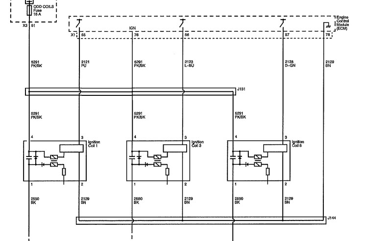
These coils aren't power or ground side switched in the typical sense, because the transistors that control primary current flow are in the coils instead of the PCM. The PCM merely controls the base of the transistor to command current flow.
The PCM does that by supplying a small voltage on the control wire for the coil. Typically around 5V - it doesn't take much. :lol: So in that sense, it's a power side switched driver? But it's not really 'power' that's being switched, so I'd hesitate to think of it that way.
I group this coil style in with Nissan/Mitsubishi/Honda three wire and VW four wire designs. They all function in basically the same way, despite the missing/extra wire. Toyota COP's are very similar except for the added IGF (feedback) circuit.
The Mitsubishi Lancer No Start case study on Premium is the perfect material for learning more about this style of coil and how they operate. Definitely watch if it you haven't already.")
www.scannerdanner.com/scannerdanner-prem...se-study-part-1.html
These coils aren't power or ground side switched in the typical sense, because the transistors that control primary current flow are in the coils instead of the PCM. The PCM merely controls the base of the transistor to command current flow.
The PCM does that by supplying a small voltage on the control wire for the coil. Typically around 5V - it doesn't take much. :lol: So in that sense, it's a power side switched driver? But it's not really 'power' that's being switched, so I'd hesitate to think of it that way.
I group this coil style in with Nissan/Mitsubishi/Honda three wire and VW four wire designs. They all function in basically the same way, despite the missing/extra wire. Toyota COP's are very similar except for the added IGF (feedback) circuit.
The Mitsubishi Lancer No Start case study on Premium is the perfect material for learning more about this style of coil and how they operate. Definitely watch if it you haven't already.
www.scannerdanner.com/scannerdanner-prem...se-study-part-1.html
The following user(s) said Thank You: Noah, Wood
Please Log in or Create an account to join the conversation.
Time to create page: 0.217 seconds