Purpose internal resistor pcm potentiometer
- autojoe
-
 Topic Author
- Offline
- Elite Member
-

- Posts: 239
- Thank you received: 7
Please Log in or Create an account to join the conversation.
- Andy.MacFadyen
-

- Offline
- Moderator
-

- Posts: 3357
- Thank you received: 1037
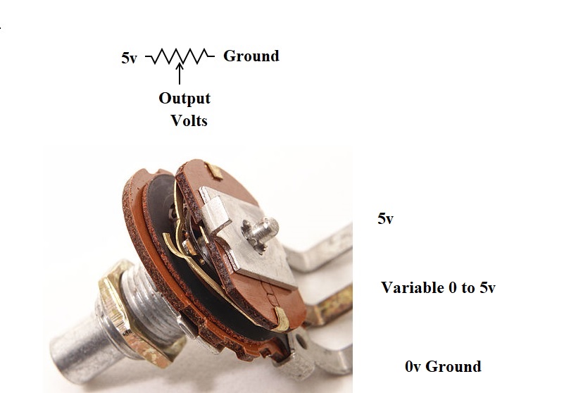
The first type of circuit found most commonly in throttle position sensors is a true potentiometer real easy to understand.
Another name for a potentiometer is a voltage divider and that is probably a more meaningful way to think of it.
The other thing to keep in mind the ECM is measuring these signals as changes voltages not currents
I am not going to into much detail but the circuits used are called a Wheatstone Bridge, Wheatstone like Samuel Morse was an developer of the early telegraph system.
Quoting Wikipedia
"A potentiometer is a three-terminal resistor with a sliding or rotating contact that forms an adjustable voltage divider. If only two terminals are used, one end and the wiper, it acts as a variable resistor or rheostat. "
In a Throttle Postion Sensor we have a closely controlled 5v ref voltage at one ended terminal and straight ground at the other end terminal while the centre pin is our variable output.
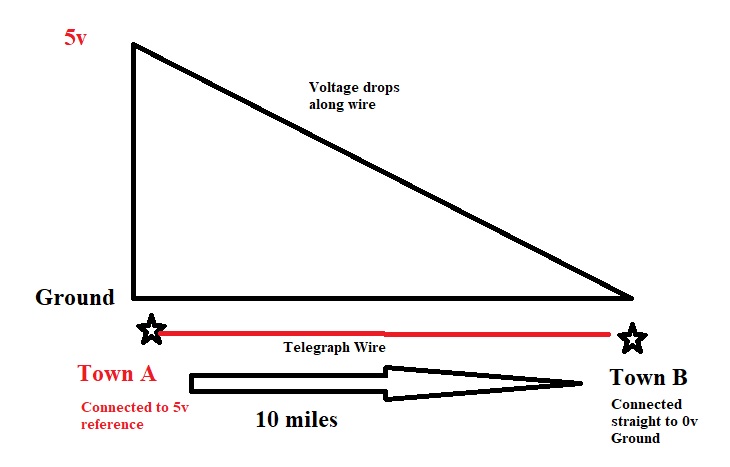
The way to think of this is if we have 2 towns connected by a telegraph wire at town A the wire is connected to a 5v reference and at town B the wire is simply connected straight to ground.
" We're trying to plug a hole in the universe, what are you doing ?. "
(Walter Bishop Fringe TV show)
Please Log in or Create an account to join the conversation.
- Andy.MacFadyen
-
- Offline
- Moderator
-
- Posts: 3357
- Thank you received: 1037
" We're trying to plug a hole in the universe, what are you doing ?. "
(Walter Bishop Fringe TV show)
Please Log in or Create an account to join the conversation.
- Andy.MacFadyen
-
- Offline
- Moderator
-
- Posts: 3357
- Thank you received: 1037
" We're trying to plug a hole in the universe, what are you doing ?. "
(Walter Bishop Fringe TV show)
Please Log in or Create an account to join the conversation.
- Andy.MacFadyen
-
- Offline
- Moderator
-
- Posts: 3357
- Thank you received: 1037
" We're trying to plug a hole in the universe, what are you doing ?. "
(Walter Bishop Fringe TV show)
Please Log in or Create an account to join the conversation.
- autojoe
-
Topic Author
- Offline
- Elite Member
-
- Posts: 239
- Thank you received: 7
Please Log in or Create an account to join the conversation.
- Andy.MacFadyen
-
- Offline
- Moderator
-
- Posts: 3357
- Thank you received: 1037
autojoe wrote: Thanks for the reply. I know about voltage dividing circuits and thermistor..... And the pcm voltage sensing and no current flow on signal wire. What is the fixed resistor between the five volt ref and the signal wire internal inside the pcm used for? Am I missing something?
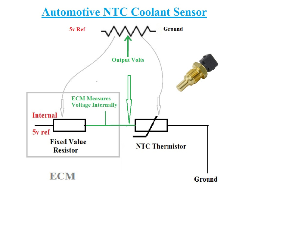
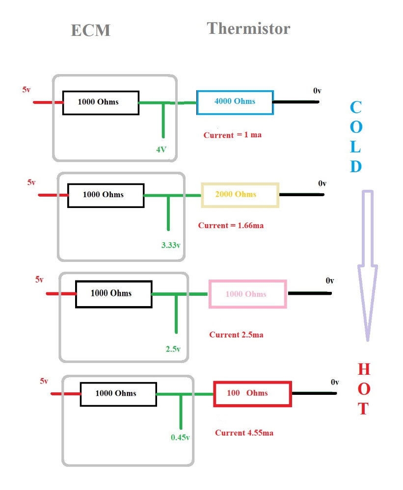
It really is all to do with voltage drop across the ECM's fixed value resistor and share of the volts drop across the thermistor.
The same current flows through both the fixed resistor in the ECU and the Temperature sensor but the way the volts drop across each resistor changes, at low temperatures more of the voltage is dropped across the temperature sensor but at higher tempersture most of the 5v is dropped across the fixed resistor inside the ECM.
" We're trying to plug a hole in the universe, what are you doing ?. "
(Walter Bishop Fringe TV show)
Please Log in or Create an account to join the conversation.
- autojoe
-
Topic Author
- Offline
- Elite Member
-
- Posts: 239
- Thank you received: 7
Please Log in or Create an account to join the conversation.
- Andy.MacFadyen
-
- Offline
- Moderator
-
- Posts: 3357
- Thank you received: 1037
" We're trying to plug a hole in the universe, what are you doing ?. "
(Walter Bishop Fringe TV show)
Please Log in or Create an account to join the conversation.
- autojoe
-
Topic Author
- Offline
- Elite Member
-
- Posts: 239
- Thank you received: 7
Please Log in or Create an account to join the conversation.
- Deejay
-
- Offline
- New Member
-

- Posts: 3
- Thank you received: 0
The voltage sensing circuit without the fixed resistor would see the 0 volts on the signal wire as either a short or an open, it doesn't know for sure which one.
On the other design, with the fixed resistor, with the presence of 5v on the signal wire, the computer knows that's an open or the sensor is unplugged. If it sees 0v, it knows right away there's a short somewhere on the signal wire. It may flag a more specific DTC.
Please Log in or Create an account to join the conversation.
- autojoe
-
Topic Author
- Offline
- Elite Member
-
- Posts: 239
- Thank you received: 7
Please Log in or Create an account to join the conversation.
- ScannerDanner
-

- Offline
- Administrator
-

- Religion says do, Jesus says done!
- Posts: 975
- Thank you received: 500
Are you a premium member? This would be the lecture you want to watch. I do my best to explain this internal resistor.autojoe wrote: I know how a thermistor works with voltage dividing circuit but I am talking about the potentiometer circuit with the fixed resistor between the 5 volt ref and the signal wire of the potentiometer and the purpose of the 5 volts on the signal wire with it disconnected.
www.scannerdanner.com/scannerdanner-prem...Potentiometers-10-15
Don't be a parts changer!
Please Log in or Create an account to join the conversation.