How to handle outputs when BOTH wires go to/come from the ECU?
- Farseer
-
 Topic Author
- Offline
- Senior Member
-

Less
More
- Posts: 43
- Thank you received: 5
1 year 3 months ago #85866
by Farseer
How to handle outputs fully powered/grounded by the ECU? was created by Farseer
Hi, all, I have a question regarding outputs that are both grounded AND sourced from the ECU - meaning, both wires on a diagram trace back to the ECU.
I've come to understand and utilise the theory SD has taught, of ground side and power side switched circuits and how to energise them.
HOWEVER, I've been itching to try energising an EGR valve that's throwing a EGR flow code.
But, as luck would have it, in both cases I couldn't. The EGRs weren't traditionally GSS/PSS. Both wires headed back to the ECU. Both wires had system voltage on them.

Now, I'm at a loss, is there anyway you guys handle such outputs? Is there even any way we might check them, other than bi-directionally controlling them?
AND would you say that this is the way outputs are being wired in newer cars or rather the exception?
I've come to understand and utilise the theory SD has taught, of ground side and power side switched circuits and how to energise them.
HOWEVER, I've been itching to try energising an EGR valve that's throwing a EGR flow code.
But, as luck would have it, in both cases I couldn't. The EGRs weren't traditionally GSS/PSS. Both wires headed back to the ECU. Both wires had system voltage on them.
Now, I'm at a loss, is there anyway you guys handle such outputs? Is there even any way we might check them, other than bi-directionally controlling them?
AND would you say that this is the way outputs are being wired in newer cars or rather the exception?
Please Log in or Create an account to join the conversation.
- Farseer
-
Topic Author
- Offline
- Senior Member
-
Less
More
- Posts: 43
- Thank you received: 5
1 year 3 months ago #86090
by Farseer
Replied by Farseer on topic How to handle outputs when BOTH wires go to/come from the ECU?
Anyone?
I've added a wiring diagram.
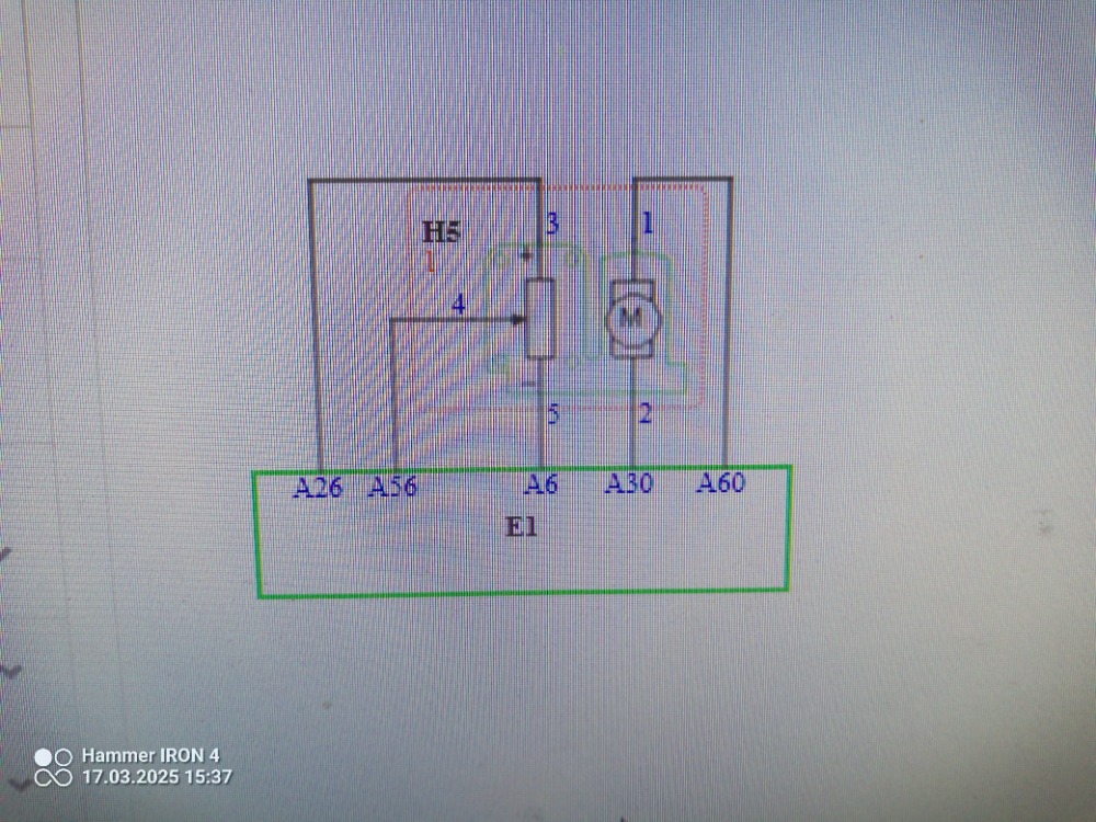
Those three wires on the left are for the potentiometer, but the wires to the motor come from the ECU.
Perhaps that'll help. I know I'm terrible at phrasing questions.
Looking at the diagram I have no idea how to determine if it's power or ground side switched. Thus, I wouldn't know how to energise an EGR, for example, to test for a flow code.
I've added a wiring diagram.
Those three wires on the left are for the potentiometer, but the wires to the motor come from the ECU.
Perhaps that'll help. I know I'm terrible at phrasing questions.
Looking at the diagram I have no idea how to determine if it's power or ground side switched. Thus, I wouldn't know how to energise an EGR, for example, to test for a flow code.
Please Log in or Create an account to join the conversation.
- Chad
-

- Offline
- Moderator
-

- I am not a parts changer.
Less
More
- Posts: 2199
- Thank you received: 741
1 year 3 months ago - 1 year 3 months ago #86101
by Chad
You haven't provided us with the Year, Make, Model, or Engine... so it is difficult to offer any vehicle-specific information.
However, if both wires lead back to the ECU, it may mean that the ECU reverses polarity to reverse the direction of the motor.
A motor needs both Power and Ground to run. Power on one wire, Ground on the other wire will make the motor run in either a clockwise, or counter-clockwise direction. If the Power and Ground are reversed, the motor will turn in the opposite direction.
If you have power on both wires, disconnect the connector and check the voltage on each wire. Use and incandescent test-light. If you have voltage that will light an incandescent test-light on ONLY ONE wire (with the connector disconnected), it would, probably, be safe to short the OTHER wire ( after reconnecting the connector) to ground energize the motor.
However, if you disconnect the connector and have voltage that will light an incandescent test-light on BOTH wires, do NOT try to short either wire to ground.
Since you are dealing with an EGR FLOW code, I would take a close look at the EGR passage that is on the INTAKE MANIFOLD side of the valve.
The hot, oily/carboned exhaust will condense when it is exposed to the cooler, lower pressure of the intake manifold. This can cause the EGR passage, on the intake manifold side of the EGR valve to become clogged, restricting EGR flow.
"Knowledge is a weapon. Arm yourself, well, before going to do battle."
"Understanding a question is half an answer."
I have learned more by being wrong, than I have by being right.")
Replied by Chad on topic How to handle outputs when BOTH wires go to/come from the ECU?
Both wires headed back to the ECU. Both wires had system voltage on them.
You haven't provided us with the Year, Make, Model, or Engine... so it is difficult to offer any vehicle-specific information.
However, if both wires lead back to the ECU, it may mean that the ECU reverses polarity to reverse the direction of the motor.
A motor needs both Power and Ground to run. Power on one wire, Ground on the other wire will make the motor run in either a clockwise, or counter-clockwise direction. If the Power and Ground are reversed, the motor will turn in the opposite direction.
If you have power on both wires, disconnect the connector and check the voltage on each wire. Use and incandescent test-light. If you have voltage that will light an incandescent test-light on ONLY ONE wire (with the connector disconnected), it would, probably, be safe to short the OTHER wire ( after reconnecting the connector) to ground energize the motor.
However, if you disconnect the connector and have voltage that will light an incandescent test-light on BOTH wires, do NOT try to short either wire to ground.
Since you are dealing with an EGR FLOW code, I would take a close look at the EGR passage that is on the INTAKE MANIFOLD side of the valve.
The hot, oily/carboned exhaust will condense when it is exposed to the cooler, lower pressure of the intake manifold. This can cause the EGR passage, on the intake manifold side of the EGR valve to become clogged, restricting EGR flow.
"Knowledge is a weapon. Arm yourself, well, before going to do battle."
"Understanding a question is half an answer."
I have learned more by being wrong, than I have by being right.
Last edit: 1 year 3 months ago by Chad.
The following user(s) said Thank You: Farseer
Please Log in or Create an account to join the conversation.
- Farseer
-
Topic Author
- Offline
- Senior Member
-
Less
More
- Posts: 43
- Thank you received: 5
1 year 3 months ago - 1 year 3 months ago #86109
by Farseer
Replied by Farseer on topic How to handle outputs when BOTH wires go to/come from the ECU?
Chad! That's actually very helpful! I hadn't thought of that, perhaps you are right!
The car is a Seat Ibiza 1.4 TDI, engine code BMS, don't remember anything else.
It actually makes sense that It could reverse the polarity. I wonder. Tomorrow when I go back to work on the car I'll definitely try out what you suggested. Thank you again, very helpful.
But a regular EGR valve that was more "traditionally" wired would do what to reverse the position? Have a spring inside?
I mixed up the cars I was doing. Both have EGR fault codes. The Seat turned out to be a faulty EGR. Because I didnt know how to energise the valve, I bidirectionally controlled it. Even though it was making a sound as if it was engaging, the signal wire for the potentiometer showed no voltage change.
I took it out and visually saw that the valve wasn't moving, despite the noise it was making.
The EGR flow code is on another car. And it'll get even stranger. The car is a Suzuki Lania, I'll get the specifics of it tomorrow.
The EGR passages are spotless. I verified that with compressed air. No obstructions.
But the EGR doesn't want to energise. Not even via scan tool. The customer swapped the old for a new and the same thing on the new one.
But, check this out. There are six wires going to the solenoid. Every single wire comes from the ECU! And you have system voltage on every single one of those six wires with the car running or KOEO. Yes, literally 14.5V on all six with KOER.
But with the connector disconnected you get other V readings. Two pins have system V and the others are either biases or 0V.
I'll check tomorrow and chime back. Never seen anything like it.
I've added the diagram. I'll get the specifics of the model tomorrow.
Thanks!
Last edit: 1 year 3 months ago by Farseer.
Please Log in or Create an account to join the conversation.
- Farseer
-
Topic Author
- Offline
- Senior Member
-
Less
More
- Posts: 43
- Thank you received: 5
1 year 3 months ago - 1 year 3 months ago #86274
by Farseer
Replied by Farseer on topic How to handle outputs when BOTH wires go to/come from the ECU?
Unfortunately, the test light lit on both accounts and did not pull the V down. So they aren't biases.
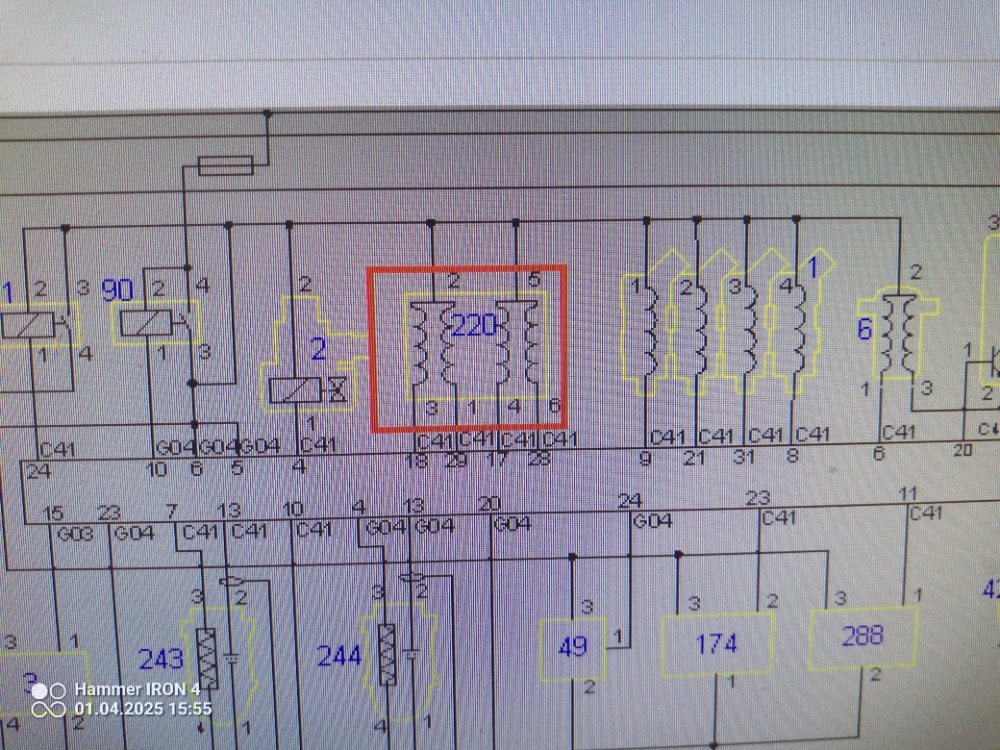
The 6 wire EGR is from a Suzuki Lania 1.6, 2001-2007, engine M16A
With the connector unplugged, as per the diagram, there are 2 system V feeds. Three more wires have 3.8V (bias) and one is 0.2v.
Plugged in, all 6 have system voltage. Never seen anything like it. There isn't even a conventional potentiometer circuit in there.
Same thing on both the old and the new.
Maybe you guys have a better wiring diagram that will show more?
Last edit: 1 year 3 months ago by Farseer.
Please Log in or Create an account to join the conversation.
- Farseer
-
Topic Author
- Offline
- Senior Member
-
Less
More
- Posts: 43
- Thank you received: 5
1 year 3 months ago #86472
by Farseer
Replied by Farseer on topic How to handle outputs when BOTH wires go to/come from the ECU?
I took the old EGR apart and everything appears to indicate it just wasn't being commanded by the ECU.
It is, indeed, a stepper type motor. So it would have to apply a ground and power and reverse it. But that can be done on two pins, no?
So what the other 4 are there for... I would expect some type of potentiometer. But that leaves one more wire.
It is, indeed, a stepper type motor. So it would have to apply a ground and power and reverse it. But that can be done on two pins, no?
So what the other 4 are there for... I would expect some type of potentiometer. But that leaves one more wire.
Please Log in or Create an account to join the conversation.
- Farseer
-
Topic Author
- Offline
- Senior Member
-
Less
More
- Posts: 43
- Thank you received: 5
1 year 3 months ago #86484
by Farseer
Replied by Farseer on topic How to handle outputs when BOTH wires go to/come from the ECU?
Sort of answered my question In the mean time.
It is possibly a 6 wire stepper motor with three coils.
And those coils are operated separately.
So there's no way to test it.
Oh well.
It is possibly a 6 wire stepper motor with three coils.
And those coils are operated separately.
So there's no way to test it.
Oh well.
Please Log in or Create an account to join the conversation.
- Farseer
-
Topic Author
- Offline
- Senior Member
-
Less
More
- Posts: 43
- Thank you received: 5
1 year 3 months ago #88168
by Farseer
Replied by Farseer on topic How to handle outputs when BOTH wires go to/come from the ECU?
For anyone Interested, as a follow up for the Seat 1.4 TDI BMS engine code.
Despite having both wires for the EGR motor coming from the ECU, when commanded to open, V on one wire drops to 0. So just like with a "typical" ground side switched circuit, but in this case both pwr and gnd come from ECU.
I guess no way to safely energise anything like that other then through scan tool.
No update on the Lania. Light didn't come back on again. Which is a shame.
The following user(s) said Thank You: Noah
Please Log in or Create an account to join the conversation.
Time to create page: 0.251 seconds