Bias Voltage on a Single Wire Knock Sensor?
- SailorBob
-
 Topic Author
- Offline
- Elite Member
-

It's a 200ms screen, the blue trace is the knock sensor at 500mv / div, the yellow is the CMP at 1v / div. Engine is idling very rough at about 500rpm with the brights, defrost and AC on:
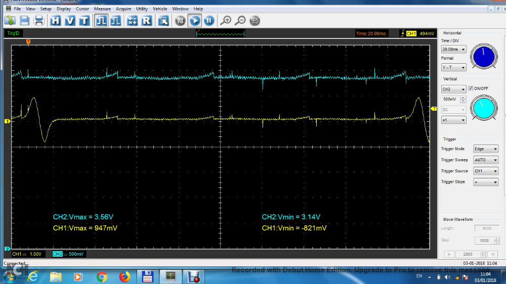
You can see matching ignition system interference in both signals, but other than that interference the knock trace seems to be a flat line at about 3.5v.
This is a single wire knock sensor grounded through it's threads to the engine block. I have two questions:
- I don't understand how a single wire sensor like this could have a bias voltage
- This engine is idling so rough during this capture that I'd expect to see some activity, yet it's pretty much flat line. Why?
You can see the full three minute capture here .
Please Log in or Create an account to join the conversation.
- Andy.MacFadyen
-

- Offline
- Moderator
-

- Posts: 3357
- Thank you received: 1037
" We're trying to plug a hole in the universe, what are you doing ?. "
(Walter Bishop Fringe TV show)
Please Log in or Create an account to join the conversation.
- SailorBob
-
Topic Author
- Offline
- Elite Member
-
Please Log in or Create an account to join the conversation.
- Tyler
-

- Offline
- Moderator
-
- Full time HACK since 2012
- Posts: 6126
- Thank you received: 1542
Are you getting any trouble codes? If this is anything like the Nissan sensors we're familiar with, then the PCM is providing a 5V signal on the knock sensor wire. The sensors resistance to ground will then pull that 5V down to 2.5V when plugged in. Higher voltages indicate an open, lower indicate a short.
I'd be tempted to lightly tap on the block with a small hammer and watch the knock sensor signal, just to see if it's capable of producing signal.
Please Log in or Create an account to join the conversation.
- SailorBob
-
Topic Author
- Offline
- Elite Member
-
I'll try giving it a knock, and maybe even removing it and try cleaning the threads.
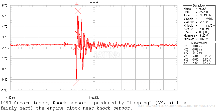
As a side note, when looking at KS waveforms on IATN I could find very few with any apparent bias voltage. One I found is this 1990 Subaru Legacy:
Please Log in or Create an account to join the conversation.
- Tyler
-
- Offline
- Moderator
-
- Full time HACK since 2012
- Posts: 6126
- Thank you received: 1542
The bias voltage thing seems to be hit or miss with different makes/models. Most GM small blocks have no bias, so the only way they test the sensor is to deliberately induce a knock and look for a response. :lol: But some older GM V6's do use a bias, and even share one bias across two sensors.
Please Log in or Create an account to join the conversation.
- SailorBob
-
Topic Author
- Offline
- Elite Member
-
Basically, with KOEO, it's showing about 3.28v on the wire. With the noise from the ignition system the scope is usually reading between 3.09v to 3.49v while running. I started tapping on various places with a small ball peen hammer with the scope set to single shot mode, KOEO, and the only place I could get a response was on the exhaust manifold near the #2 cylinder. The KS is installed on the opposite side of the block next to the #2 cylinder position. Here's what it looked like:
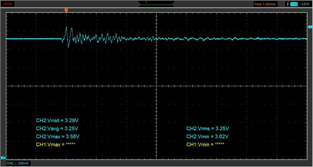
As you can see, I barely get any response at all, 3.02v low and 3.58v high. It may be I'm tapping too far away, or not hard enough, I've never done this before, but you can hear my vigorous tapping in the video. I tried tapping with the engine running also and couldn't see anything, the response, if any, was totally swallowed by the ignition noise.
I see that the waveform that I found for the Suburu shows way more response, but I think he was also tapping on the block right next to the sensor, which I can't really do due to space constraints.
Please Log in or Create an account to join the conversation.
- SailorBob
-
Topic Author
- Offline
- Elite Member
-
Tyler wrote: The Snap-On Troubleshooter says that you'll get a P0325 Knock Sensor Fault code when the signal voltage goes below 1.2V or over 3.7V after engine startup. :huh: Your 3.5V is a little bit too close to 3.7V for comfort.
Are you getting any trouble codes? If this is anything like the Nissan sensors we're familiar with, then the PCM is providing a 5V signal on the knock sensor wire. The sensors resistance to ground will then pull that 5V down to 2.5V when plugged in. Higher voltages indicate an open, lower indicate a short.
By the way, I've never seen a knock code on this vehicle, although it's not OBDII since it's a European model. Also, couldn't higher voltage also be caused by a bad ground between the sensor and the block?
Please Log in or Create an account to join the conversation.
- Tyler
-
- Offline
- Moderator
-
- Full time HACK since 2012
- Posts: 6126
- Thank you received: 1542
The high-ish bias could definitely be from poor sensor ground. BUT, remember that I don't have a good spec on this system. What you're seeing may be normal. :blink:
Please Log in or Create an account to join the conversation.
- SailorBob
-
Topic Author
- Offline
- Elite Member
-
Actually, I'm not sure why I couldn't pick up the amperage, as that comes out to 5.9 microamps which my ohmmeter should be able to measure.
Also not sure why my 5v ref is only 4.59v and if that's a problem or not.
Please Log in or Create an account to join the conversation.
- Andy.MacFadyen
-
- Offline
- Moderator
-
- Posts: 3357
- Thank you received: 1037
Sensor resistance around 550,00 ohms.
Normal Oscilloscope 1,000,000 ohms
Good quality digital Voltmeter 10,000,000 ohms
Reading the sensor output with either an oscilloscope or to a lesser extent a multimeter will put aelectrical load on the sensor pull down the sensor output voltage.
" We're trying to plug a hole in the universe, what are you doing ?. "
(Walter Bishop Fringe TV show)
Please Log in or Create an account to join the conversation.
- SailorBob
-
Topic Author
- Offline
- Elite Member
-
Please Log in or Create an account to join the conversation.
- Andy.MacFadyen
-
- Offline
- Moderator
-
- Posts: 3357
- Thank you received: 1037
" We're trying to plug a hole in the universe, what are you doing ?. "
(Walter Bishop Fringe TV show)
Please Log in or Create an account to join the conversation.