5V reference circuit issues, Dodge Durango 2013
- darkseca
-
 Topic Author
- Offline
- New Member
-

- Posts: 9
- Thank you received: 1
I have a Dodge Durango 2013 with 3.6 V6 engine.
The car occasionally goes in limp mode. The problem becomes more and more frequent. Recently throws a CEL after 5-30 minutes of driving.
Codes (the most frequent ones):
- P1628 - SENSOR REFERENCE VOLTAGE 2 CIRCUIT ERRATIC
- P0652 - 5 Volt Sensor Reference 2 Circuit Low
- P0344 - Camshaft Position Sensor Circuit Intermittent
- P0369 - Camshaft Position Sensor 2 Circuit Intermittent Bank 1
- P0129 - Barometric Pressure Out-Of-Range Low (MAP sensor signal wire is below 2.28v)
- P2127-ACCELERATOR PEDAL POSITION SENSOR 2 CIRCUIT LOW
- P0394 - Camshaft Position Sensor Intermittent - Bank 2 Sensor 2
- P0123 – throttle position sensor circuit high
Sometimes I’m getting also other codes: C1203, U1400, U1404, C2916, P0118, P0198, P0523, P0222, P2122, P0108
What was done:
- New alternator installed
- Remanufactured PCM installed (due to a problem with voltage regulator after alternator failure)
- New batter installed
- Engine harness inspected visually
- All sensors that use 5V signals were replaced: 2x camshaft sensor, crankshaft sensor, TPS, MAP sensor, accelerator pedal sensor, oil pressure sensor
- Spark plugs replaced (regular maintenance)
- Wiring harness tested for continuity, shorts to ground and shorts to 12V from every sensor to PCM. I did it with an ohmmeter, with no load.
- Both 5V signals (K855 and K856) checked at sensors (engine off)
- Both 5V signals traced with a scope (engine on)
- Ground point near the PCM cleaned. I found a dangling engine ground strap, that I haven’t replaced yet.
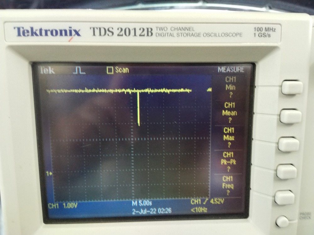
There is one thing that looks suspicious to me. I can see some spikes in voltage, up to 1.5V, most of them are downwards but there are some upwards. There are also some slight fluctuations. Signals from both circuits are almost identical. What do you guys think?
This is what I have observed:
This is so frustrating! Thanks in advance for any help!
Please Log in or Create an account to join the conversation.
- Poq600
-
- Offline
- Junior Member
-

- Posts: 20
- Thank you received: 2
Please Log in or Create an account to join the conversation.
- Poq600
-
- Offline
- Junior Member
-
- Posts: 20
- Thank you received: 2
Please Log in or Create an account to join the conversation.
- darkseca
-
Topic Author
- Offline
- New Member
-
- Posts: 9
- Thank you received: 1
Limp mode triggered by a tranny soenoid?
Why do you think it's tranny solenoid? How do I check this?
Please Log in or Create an account to join the conversation.
- darkseca
-
Topic Author
- Offline
- New Member
-
- Posts: 9
- Thank you received: 1
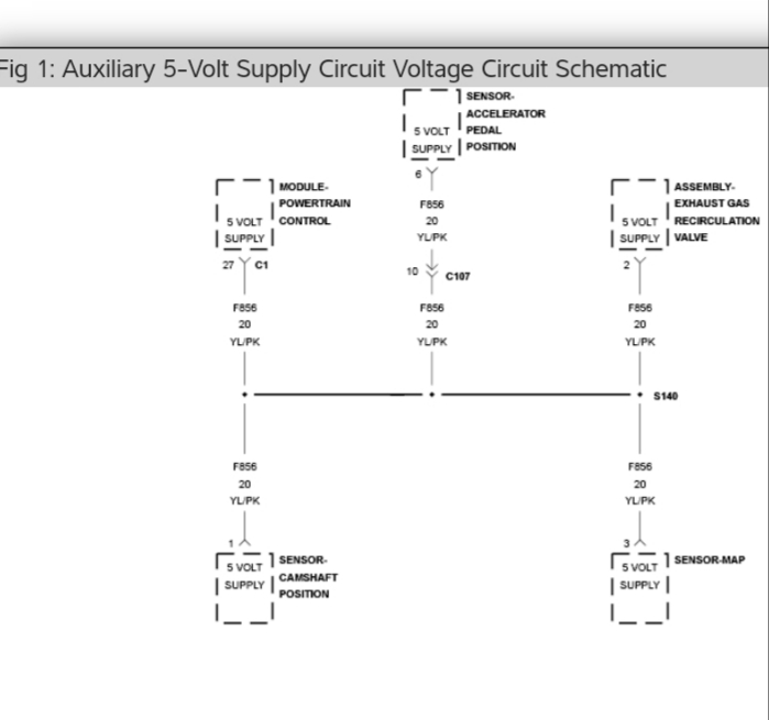
Interesting. Just an observation. Those are 5v reference signals right? At pcm? Not sure of dodge wirng set up but it seems you're actually measuring the same signal at 2 different points. It might be split outside the pcm but actually coming from one source. I also noticed the positive spikes are coming every 7th sweep which seems to be every 15 seconds or so. Maybe a voltage spike from a collapsing solenoid that's energizing due to pcm strategy that has a bad ground wire? Could the purge solenoid or another solenoid be suspect at idle ? Hope that helps.
Yes, these are signals from two 5V signals from the PCM. It was measured at the APPS sensors because of easy access. The signals look similar, because I used a ground point on the body, and not sensor grounds. Positive spikes every 15s correspond roughly to the activation of the AC compressor.
I traced the singal using 5V and the ground at the MAP sensor and it is much more stable.
I managed to register the moment of limp mode triggering. There was a negative spike at the moment of shifting to D. I start to think that the problem is not the 5V circuit shorted out, but a sudden current draw, that the voltage regulating circuit in the PCM cannot compensate. The 5V ref signal codes are thrown because this circuit is very sensitive to voltage variations.
I’m going to trace both 5V and PCM input voltage to see if there is a correlation and if there is a drop in voltage on both circuits at the moment when the limp mode is triggered. Tracing the root cause seems to be impossible, therefore I consider two solutions:
- Cut off the 5V signal from the PCM and using an external voltage regulator for 5V sensors.
In case this doesn’t work, I will try to solder in a voltage stabilizing circuit in the 5V circuit.
Please Log in or Create an account to join the conversation.
- Poq600
-
- Offline
- Junior Member
-
- Posts: 20
- Thank you received: 2
The 5v reference spikes seem to happen when loading the engine, compressor and shifter. Those spikes could have been normal using engine grounds. Not sure of that.I guess you fixed that ground strap ?
I am btw just a diy guy trying to think outside the box. It seems You had so many codes initially that merited parts changing with no help. Bad parts are common.i personally would start fresh with old parts reinstalled. Did all the initial codes come back after clearing them? Try tackling the not so obvious, like cam crank correlations. Stuff like that..hope that helps.
Please Log in or Create an account to join the conversation.
- Noah
-

- Offline
- Moderator
-

- Posts: 5033
- Thank you received: 1119
I like to clear the code salad, reproduce the fault, and go after the first code(s) that set to narrow down the possibilities a little.
Please Log in or Create an account to join the conversation.
- darkseca
-
Topic Author
- Offline
- New Member
-
- Posts: 9
- Thank you received: 1
So is it the tranny going into limp mode, causing no upshifting after you shift to drive ? Or is it the engine going into limp mode restricting higher rpms and engine power? That would narrow what direction to take next, wouldn't you agree?
The 5v reference spikes seem to happen when loading the engine, compressor and shifter. Those spikes could have been normal using engine grounds. Not sure of that.I guess you fixed that ground strap ?
I am btw just a diy guy trying to think outside the box. It seems You had so many codes initially that merited parts changing with no help. Bad parts are common.i personally would start fresh with old parts reinstalled. Did all the initial codes come back after clearing them? Try tackling the not so obvious, like cam crank correlations. Stuff like that..hope that helps.
- When the car goes into limp mode, the power is reduced, there is a CEL, traction control light and a red bolt on, rpms and engine power are restricted. You can upshift, however with the power reduced so much the car barely moves forward so it just doesn't happen unless you shift it manually.
- I don't know what triggers the limp mode and what causes the spikes. Yesterday I tried turning lights on, AC, turning the steering wheels (I have electric PS pump), shifting from P to D or to R and I couldn't force the car go into limp mode. Then it just happened, but I don't know why.
- I have a new ground strap, but the nipple on the engine side that the strap is normally attached to is stripped. I didn't figure out how to attach it. The spikes are negative, so I'm not sure if a ground strap would be much help here.
- All codes are related to the 5 circuits. Some sensors are difficult to reach, for example the oil pressure sensor and the camshaft require the manifold to be removed. It's quite a job, I would prefer not coming back there. I installed Mopar parts to avoid the risk. I also tried 3 other MAP sensors and 4 camshaft sensors.
Please Log in or Create an account to join the conversation.
- darkseca
-
Topic Author
- Offline
- New Member
-
- Posts: 9
- Thank you received: 1
Do all those codes come back at the same time?
I like to clear the code salad, reproduce the fault, and go after the first code(s) that set to narrow down the possibilities a little.
I have cleared the codes hundreds of times already to find a pattern... Usually the first that appears is the P0652 or P1628 Then it could be any code for 5V sensors, pretty much all codes related to camshaft operation, APPS, MAP, etc and U1400 and U1404 that are the consequence of other codes, I believe.
I managed to reproduce the problem by shorting the MAP sensor ground wire to 5V wire. The limp mode was activated and I got the codes P0652, P2127 (APPS), P1400 and P1404.
By the way, I caught the moment of triggering the limp mode already twice, its always very short negative spike. The yellow signal is the 5V at the MAP sensor and the blue one is 12V at PCM fuse in the TIPM.

Please Log in or Create an account to join the conversation.
- Noah
-
- Offline
- Moderator
-
- Posts: 5033
- Thank you received: 1119
Please Log in or Create an account to join the conversation.
- darkseca
-
Topic Author
- Offline
- New Member
-
- Posts: 9
- Thank you received: 1
ALL of them have been already replaced, the PCM was replaced too. The wiring harness was tested with a multimeter, with no load (no voltage drop tests). I also tried to wiggle the wires and the connectors, while monitoring the 5V signal with the oscilloscope. The signal was very stable.
The 5V signal was pulled to around 2.5V. I can read the voltage from service freeze frames on the MAP sensor and typically it's around 2.7V.
Please Log in or Create an account to join the conversation.
- Poq600
-
- Offline
- Junior Member
-
- Posts: 20
- Thank you received: 2
Anyway, dig deeper if you can on wiring diagrams to see if any junction connectors are involved between sensors and the pcm.
Also , Paul shows us that the ohmeter checks with no loading will give false continuity integrity, fooling us to think all is good.Green crusties somewhere is surely a strong suspect here since changing parts didn't help.
We know that a faulty sensor can pull ref circuits down. Is it possible a good sensor will then load a bad wiring situation causing a dtc to show up when ref circuit is skewed? Try unplugging the sensors one at a time anyway, to see if anything changes.
Please Log in or Create an account to join the conversation.
- darkseca
-
Topic Author
- Offline
- New Member
-
- Posts: 9
- Thank you received: 1
I know that Chrysler TIPMs are prone to failure, but I don’t see how I can rule it out without buying a new one, and these are pretty expensive. I checked the voltage on 12V feed from TIPM to PCM and it’s OK.
I agree that a load test would work better, but in this case all sensors need to be disconnected, some of them are very difficult to reach. For example, you need to remove the intake manifold to get to one of the camshaft sensor and to the oil pressure sender or even to disconnect them. It’s a hell of a job on this car. To trigger the limp mode and to see any spikes, the engine must be running. Also, the problem is intermittent, it normally occurs once every 15-30 minutes when you drive the car. Instead, I have monitored the voltage with an oscilloscope while wiggling the harness and the connectors, I spend a lot of time doing this with engine running and never managed to see a thing.
I will still try to capture the spike to see better its form but given that these are very rare and short events, and does not occur due to mechanical action, I start to doubt that this is a bad wiring situation.
What I haven’t done (but probably should have) is replacing the sensors that do not use the 5V feed wires but share the ground wires with the rest the sensors. These would be the temperature sensors (oil, air, coolant) in the circuit.
Please Log in or Create an account to join the conversation.
- Poq600
-
- Offline
- Junior Member
-
- Posts: 20
- Thank you received: 2
Please Log in or Create an account to join the conversation.
- darkseca
-
Topic Author
- Offline
- New Member
-
- Posts: 9
- Thank you received: 1
The problem was solved in August and I've realized that I didn't post the solution... So here it goes:
I got my hands on Chilton repair manuals and I found out that there is one more sensor in the 5V circuit (K856) that I didn't know about, that is a fuel tank pressure sensor. This sensor is on the top of the fuel tank, and it’s a pain to get to it, you need to drop the exhaust, driveshaft, disconnect the fuel lines…
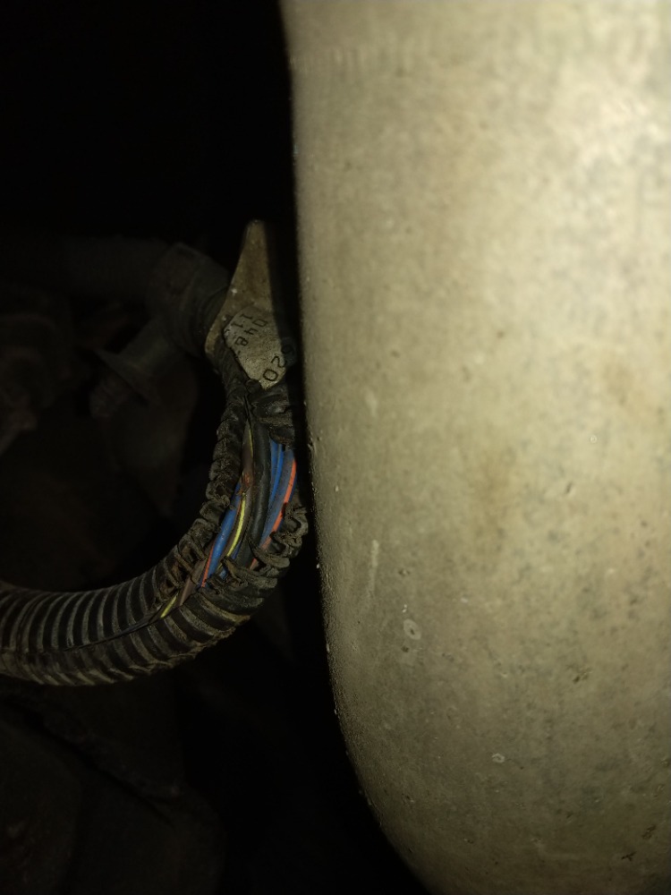
I got so frustrated, again!! I was about to cut the wires at the PCM and install a new ones from the PCM to each sensor, but if there is an unverified sensor that you can get to, the whole work makes no sense. But I crawled under the car to see if at least I can cut the wire close to this sensor and and found out that the harness near the tank is hanging down and touching the exhaust. Can you see this yellow/brown wire? Yep, this is the troublemaker, the 5V ref signal wire. The wire protector melted and the isolation on the wire was damaged shorting out the entire 5V circuit to the ground from time to time.
The car is repaired and back on the road.Thank you all for your help!!
Please Log in or Create an account to join the conversation.