2005 Ford Taurus SEL, Duratec, AX4N Trans, 231,000 miles P0708 Code
- popoften
-
 Topic Author
- Offline
- Elite Member
-

- Posts: 228
- Thank you received: 22
P0708: "Transmission Range Sensor High Input"
The car runs beautifully, and is showing no driveability or any other symptoms other than a digital message that pops up occasionally with a chime that says "Check Transmission". Stored codes are a P0430 and a pending P0430, which I assume are not relevant to the P0708. I have the factory wiring diagrams, but not much service information. I did a visual inspection of the Trans Range Sensor and wires/connector and nothing looks amiss, and input power on the blk/yellow and Brown/Pink wires is fine in KO and START respectively. I don't have detailed enough service information to know what I should be reading on the signal wires to the PCM. Any ideas would be appreciated!
~ Pop
Please Log in or Create an account to join the conversation.
- Tyler
-

- Offline
- Moderator
-

- Full time HACK since 2012
- Posts: 6115
- Thank you received: 1539

I grabbed the relevant bits out of SI for us. Uploading pictures isn't working perfectly right now.

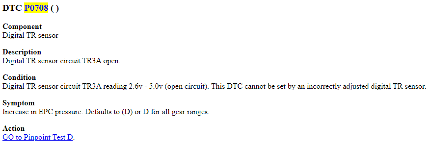
DTC P0708 ( )
Component
Digital TR sensor
Description
Digital TR sensor circuit TR3A open.
Condition
Digital TR sensor circuit TR3A reading 2.6v - 5.0v (open circuit). This DTC cannot be set by an incorrectly adjusted digital TR sensor.
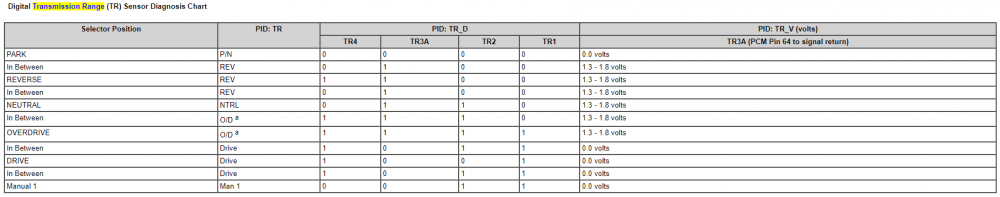
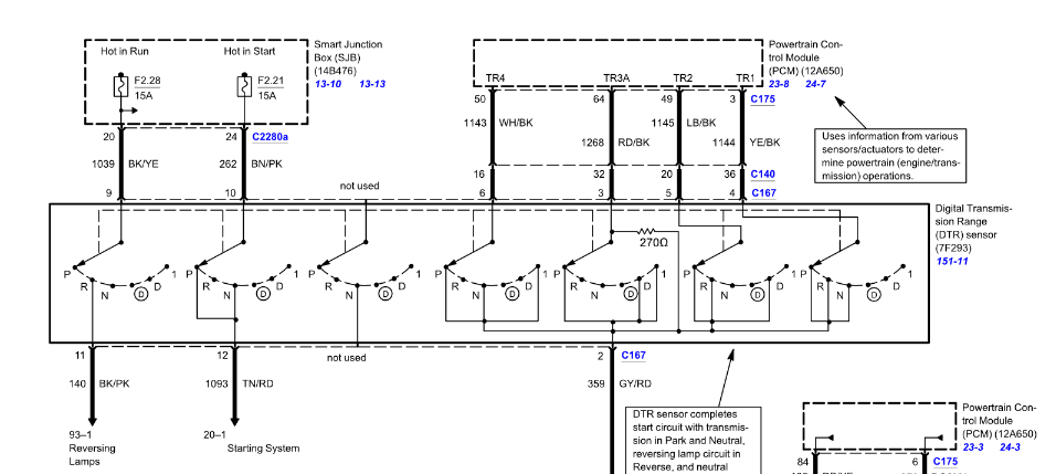
So, according to that, this code has specifically to do with the TR3A circuit. I attached the diagram. I also attached a Transmission Range sensor diagnostic chart that spells out what TR3A should read in each shifter position.
Basically, TR3A should never read more than 1.8V (or 2.6V, according to the code set criteria). I'd probably start with connecting your multimeter to the red/black wire at the range sensor, KOEO, and shift into Overdrive. Block the wheels for safety.
") Monitor the voltage while gently wiggling the sensor connector, the harness and the sensor itself. When you can make the TR3A voltage go high, you're in the right area.
Monitor the voltage while gently wiggling the sensor connector, the harness and the sensor itself. When you can make the TR3A voltage go high, you're in the right area.Alternately, you can have the multimeter on the windshield while you cycle the shifter between Drive and Overdrive. TR3A should consistently read zero or 1.3 - 1.8V. If you start getting erratic readings, you're likely looking at a failing range switch.
Please Log in or Create an account to join the conversation.
- popoften
-
Topic Author
- Offline
- Elite Member
-
- Posts: 228
- Thank you received: 22
Pop
Please Log in or Create an account to join the conversation.
- popoften
-
Topic Author
- Offline
- Elite Member
-
- Posts: 228
- Thank you received: 22
Please Log in or Create an account to join the conversation.
- Tyler
-
- Offline
- Moderator
-
- Full time HACK since 2012
- Posts: 6115
- Thank you received: 1539
Tyler, I followed the procedure you provided. All the voltages were to spec per the diagram, about 1.6 volts, but when I put the gearshift at "1" I kept getting a reading of 6.87 volts.
Well isn't that interesting. :huh: If I understand the wiring diagram correctly, that adds up to a resistive contact in the switch itself.
Or are there other tests i can do to confirm?
The only other test to do is to monitor the grey/red wire under the same conditions. That's the ground for the range switch. It should read 100mV or less, regardless of what you're doing with the shifter.
If you get excessive voltage on that circuit while manipulating the shifter, dig deeper into a harness or PCM problem. If the voltage remains less than 100mV, stick a fork in the range switch, 'cause it's done. ")
Please Log in or Create an account to join the conversation.
- Matt T
-
- Offline
- Platinum Member
-

- Posts: 751
- Thank you received: 276
Tyler, I followed the procedure you provided. All the voltages were to spec per the diagram, about 1.6 volts, but when I put the gearshift at "1" I kept getting a reading of 6.87 volts.
Well isn't that interesting. :huh: If I understand the wiring diagram correctly, that adds up to a resistive contact in the switch itself.
If I'm reading the code definition correctly it's a 5V pull down circuit that is getting >5V from somewhere. Possibly leakage from the reverse light circuit inside the switch. Could try pulling F2.28 to see if the voltage goes away.
Please Log in or Create an account to join the conversation.
- popoften
-
Topic Author
- Offline
- Elite Member
-
- Posts: 228
- Thank you received: 22
PS Oh wait. I see it is a fuse.
thanks!
Please Log in or Create an account to join the conversation.
- Tyler
-
- Offline
- Moderator
-
- Full time HACK since 2012
- Posts: 6115
- Thank you received: 1539
If I'm reading the code definition correctly it's a 5V pull down circuit that is getting >5V from somewhere. Possibly leakage from the reverse light circuit inside the switch. Could try pulling F2.28 to see if the voltage goes away.
That's a good idea.
From what I understand, the TR3A circuit gets 5V, but all the other switches get 9V. Not sure why they thought that was a good idea...
Anyway, that could also be the source of the excessive voltage.
Please Log in or Create an account to join the conversation.
- popoften
-
Topic Author
- Offline
- Elite Member
-
- Posts: 228
- Thank you received: 22
I guess it’s a good thing that though I unbolted the old TRS I couldn’t actually get it out. Seems to be stuck. I’ll bolt it back down, reconnect the harness and shift cable and do that additional test.
If TRS is confirmed as bad, just how does this thing come out other than removing the bolts and disconnecting the shift cable? I do not see any kind of snap ring or c clip on the shaft. But then again maybe I’m looking at it wrong? I am reluctant to just go at this thing wirh a pry bar lest I break or bend something.
Any insights appreciated!
Thx Pop
Please Log in or Create an account to join the conversation.
- popoften
-
Topic Author
- Offline
- Elite Member
-
- Posts: 228
- Thank you received: 22
Please Log in or Create an account to join the conversation.
- Tyler
-
- Offline
- Moderator
-
- Full time HACK since 2012
- Posts: 6115
- Thank you received: 1539
I guess it’s a good thing that though I unbolted the old TRS I couldn’t actually get it out. Seems to be stuck...
...If TRS is confirmed as bad, just how does this thing come out other than removing the bolts and disconnecting the shift cable? I do not see any kind of snap ring or c clip on the shaft. But then again maybe I’m looking at it wrong? I am reluctant to just go at this thing wirh a pry bar lest I break or bend something.
Service info says it should come right out after unbolting it. :lol: If I were you, I'd apply your favorite flavor of penetrating oil to the shift shaft and let it cook for now. Might help? Probably won't, but at least you can say you tried. :silly:
As I’ve been working on this, I’ve noticed that the heater hose assembly is leaking in several places. One place is the plastic T fitting near the transmission range sensor. There are a couple of other leaky places where metal meets rubber. Is it permissible, as was done in the old days, to just pinch off the inlet and outlet of the heater hose, so that the car can be driven until the heater hose assembly I have ordered comes in? It’s going to take a few days and I’d like to be able to use the car. However I do not know if that’s gonna throw off the computer and or sensors having to do with the coolant temperature. What do you guys think?
I'm honestly not sure.
 Older Tauri had a heater core bypass path built into the plumbing, so pinching off the hoses was no biggie. This one is different, IIRC.
I doubt you'd screw with any sensors or cause fault codes, BUT you may change how the thermostat operates. Some designs rely on the flow from the heater core to correctly warm the thermostat so it opens at the right time. I don't know if this is designed that way, just something to be aware of.
Please Log in or Create an account to join the conversation.
- Noah
-

- Offline
- Moderator
-
- Give code definitions with numbers!
- Posts: 5005
- Thank you received: 1116
I like to use some penetrating oil and I have a soft plastic hammer bit for my air hammer. I set the hammer to tickle and vibrate the top of the shaft while gently prying upward on the range sensor.
I broke many until I figured that out.
"Ground cannot be checked with a 10mm socket"
Please Log in or Create an account to join the conversation.
- popoften
-
Topic Author
- Offline
- Elite Member
-
- Posts: 228
- Thank you received: 22
Please Log in or Create an account to join the conversation.