Need help with Airbag Light Circuit.
- Chad
-
 Topic Author
- Offline
- Moderator
-

- I am not a parts changer.
- Posts: 2173
- Thank you received: 727
A scan of codes found B0101 - D squib circuit OPEN, and B1181- D squib (2nd step) circuit OPEN. I, also, noticed that the horn and steering-wheel radio controls did not work. My first thought was the Clock-spring. I disconnected the connector, at the clock-spring, and checked resistance of the D squib circuits, in the clock-spring. The circuits, in the clock-spring were good. Next, I disconnected the connectors at the Airbag Sensor Assembly module. With both ends of the harness disconnected, I check continuity of the D squib circuits, form end to end. Continuity was good. The circuits were not OPEN.
Next, I check continuity between D- and D+, as well as D2- and D2+. With both ends of the harness disconnected, I expected the read OL MΩ. What I found was the - and + wires of D squib and D (2nd stage) squib shorted together.
I called the customer to request time to pull the dash, and/or steering column, to investigate/locate what I believed to be a crushed wiring harness. I, also, mentioned the non-functioning horn and steering wheel controls. He declined to authorize more time, and said that he would investigate my findings, himself.
A week later, it is back. Again, he wants the airbags "Configured". He has found, and fixed the horn and radio problem. However, the Airbag light is still on. I scanned the codes and, not surprisingly, found B0101 and B1181. This time, however, when I cleared the codes they did not return. But, the Airbag light is STILL on. I have not done any further testing, yet. My first stop was Service Information.
This brings me to the purpose of this post. I need help understanding this, seemingly, simple diagram. It looks, to me, like power comes from the Battery, through the ignition switch, to the collector of the transistor. It, then, passes through a resistor, and then to the Base of the transistor. This is what confuses me. If the Base has power, then power can flow from the Collector, to the Emitter. This makes me think that the SRS light WILL be illuminated ANY time the ignition is in the Start/Run posisions. Does the resistor, before the Base, prevent the transistor from switching on? If so, what is the purpose of this? I would assume that the Airbag Sensor Assy Center would power the Base, turning on the Airbag Light.
 As I am creating this post, I am wondering if it is possible, instead, that the Airbag Sensor Assy Center provides a GROUND, pulling down the power to the Base turning OFF the light. This, in my mind, could possibly explain the purpose of the resistor, before the Base.
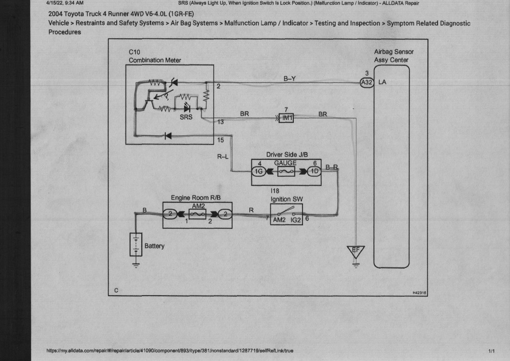
I have questions for the Owner but, I want to understand this schematic before I call.
"Knowledge is a weapon. Arm yourself, well, before going to do battle."
"Understanding a question is half an answer."
I have learned more by being wrong, than I have by being right.
")
Please Log in or Create an account to join the conversation.
- Matt T
-

- Offline
- Platinum Member
-

- Posts: 751
- Thank you received: 276
www.electronics-tutorials.ws/transistor/tran_3.html
Also FYI.....
www.safetyrestore.com/airbag-module-rese...ag-module-reset.html
Please Log in or Create an account to join the conversation.
- VegasJAK
-

- Offline
- Platinum Member
-
- Silencing the Parts Cannon
- Posts: 566
- Thank you received: 140
The transistor depicted on the diagnostic chart does not show they type of transistor it is but the schematic does...notice the arrow pointing from the emitter towards the base... its a PNP transistor which works from a ground at its base. It uses a small base current and negative base voltage to control the larger emitter to collector current. PNP's only work when both base and collector are negative with respect to the emitter. Sorry if I get this part wrong, I'm surmising; as the SRS is lit on startup, the LA circuit is off. When active, LA sends voltage to the transistor base which shuts it off and the SRS light goes out.:whistle: I hope someone who's in the know checks me and rings the bell for school to start.")
"an open mind let's knowledge flow in and wisdom flow out for a man who has neither never listens to those who have both".
Please Log in or Create an account to join the conversation.
- Chad
-
Topic Author
- Offline
- Moderator
-
- I am not a parts changer.
- Posts: 2173
- Thank you received: 727
I found more information that referred to a "Source Voltage Drop" mode.
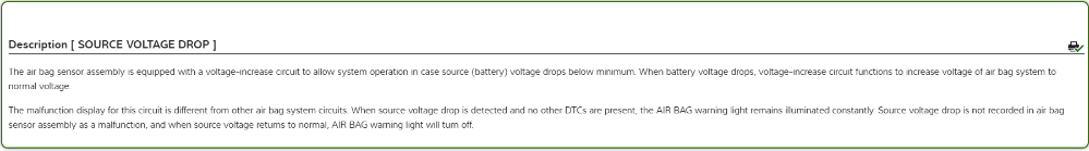
So, I checked the source voltage, and this is not the issue.
This vehicle has side airbags, which gives it an additional warning light that is not present in the original diagram posted diagram.
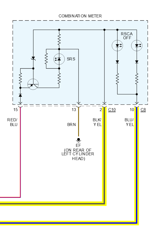
Seeing the diagram that has the RSCA (Roll-over Sensor Curtain Airbag) Off light left me with more questions. This light functions, properly, in the instrument panel. It comes on with the key, then goes off. The LA circuit is common between both LED's (SRS and RSCA OFF). The Airbag Sensor assembly was accessible so, I was able to back-probe the RSCA OFF light, at that location.
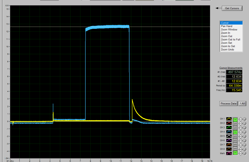
YELLOW is the LA circuit. BLUE is RMIL (RSCA OFF) Control. The waveform starts with key off, light off. Key off, the BLUE trace sits at -500 mV. YELLOW near-zero ground. Then, Key on. At Key on, the BLUE trace rises to about 250 mV, while the Yellow (LA) trace rises to 50 mV. The "RSCA OFF" light is bright. Three seconds later, the light goes out, and the BLUE trace rises to 12.6 V. :woohoo: This didn't help me understand a damn thing. :dry: Just leaves more questions. When the BLUE trace falls back to -500 mV, that is where I turned the key back off.
Fortunately, Matt T threw me an FYI than changed my direction. (Thank you, Matt.) I, now, believe that the Airbag light remains on because the SRS module was not replaced, and has recorded Crash Data. When the customer requested an airbag "Configuration", he knew more than me and was asking for the Crash Data to be cleared. Clearing the data "Virginizes" the module, and allow the light to turn off, indicating a healthy Airbag system. Otherwise, the SRS module must be replaced. Clearing the Crash Data can be done by Reading, editing, and re-writing the SRS EEPROM. I have an IM608 and was hopeful that I could do this. However, that doesn't seem to be the case.
I am going to do a little more homework but, I may have to throw in the towel, on this one.

"Knowledge is a weapon. Arm yourself, well, before going to do battle."
"Understanding a question is half an answer."
I have learned more by being wrong, than I have by being right.
Please Log in or Create an account to join the conversation.
- juergen.scholl
-

- Offline
- Platinum Member
-
- Active partschanger
- Posts: 1233
- Thank you received: 462
late to the party but here is my take:
As you mentioned because of the crash data stored in the control unit the airbag light stays on. Indeed it needs to be virginized to get the light off. I have done this before, complex but not complicated. You will need an appropriate programmer and to know where the crash data specifically is stored in the dump (dump is the name given to the read/extracted memory). There are automated programs that will help you finding the specific memory and manipulating the information, I could help you with this..., there are also online services available.
Now the BIG BUT:
In your place this a huge responsibility/liability issue. I told you to have this done before but hey, this is Mexico...
Some control units do contain crash sensors, acceleration sensors etc that could get affected during an event, you don't want to find out the hard way. I have not seen a single manufacturer allowing repair of his control units, they categorically indicate replacement.
In this case I'm not with Bob Dylan, think twice.
An expert is someone who knows each time more on each time less, until he finally knows absolutely everything about absolutely nothing.
Please Log in or Create an account to join the conversation.
- Chad
-
Topic Author
- Offline
- Moderator
-
- I am not a parts changer.
- Posts: 2173
- Thank you received: 727
You will need an appropriate programmer and to know where the crash data specifically is stored in the dump (dump is the name given to the read/extracted memory). There are automated programs that will help you finding the specific memory and manipulating the information, I could help you with this...
I would love some guidance.
As I mentioned, I have an IM608 with a programmer. The IM608 has pre-loaded Vehicle configurations for reading/writing chips. However the 4 Runner is not one of them. I have read that the IM608 programmer can be used without the IM608. It connects via USB. Maybe, if I had different laptop-based software that I could use the programmer with, I could create a dump...if I can determine the Chip ID. Any software, that you may know of, would be appreciated. I will keep digging.
"Knowledge is a weapon. Arm yourself, well, before going to do battle."
"Understanding a question is half an answer."
I have learned more by being wrong, than I have by being right.
Please Log in or Create an account to join the conversation.
- juergen.scholl
-
- Offline
- Platinum Member
-
- Active partschanger
- Posts: 1233
- Thank you received: 462
pm me an e-mail addres if you wanted and I¨ll send you a program to virginize the dump.
An expert is someone who knows each time more on each time less, until he finally knows absolutely everything about absolutely nothing.
Please Log in or Create an account to join the conversation.
- Chad
-
Topic Author
- Offline
- Moderator
-
- I am not a parts changer.
- Posts: 2173
- Thank you received: 727
"Knowledge is a weapon. Arm yourself, well, before going to do battle."
"Understanding a question is half an answer."
I have learned more by being wrong, than I have by being right.
Please Log in or Create an account to join the conversation.
- juergen.scholl
-
- Offline
- Platinum Member
-
- Active partschanger
- Posts: 1233
- Thank you received: 462
An expert is someone who knows each time more on each time less, until he finally knows absolutely everything about absolutely nothing.
Please Log in or Create an account to join the conversation.
- Ben
-
- Offline
- Platinum Member
-
- Posts: 1098
- Thank you received: 215
Sent from my SM-G781V using Tapatalk
Please Log in or Create an account to join the conversation.
- jreardon
-
- Offline
- Platinum Member
-
- Posts: 521
- Thank you received: 198
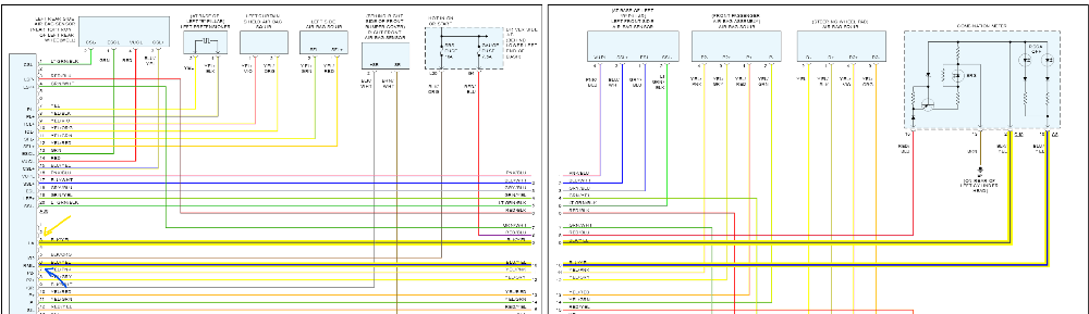
That colored diagram with the RSCA is wrong. Here's the correct one:

Also the resistor between emitter and base, current limits the zener diode while the SRS is grounding the LA circuit.
The real question is why did the engineers design the SRS light circuit like that, and not keep it simple like the RSCA light?
Please Log in or Create an account to join the conversation.