Help us help you. By posting the year, make, model and engine near the beginning of your help request, followed by the symptoms (no start, high idle, misfire etc.) Along with any prevalent Diagnostic Trouble Codes, aka DTCs, other forum members will be able to help you get to a solution more quickly and easily!
Help reading CCD Bus bad waveform - 2000 Dodge "No Bus"
- Seanerz
-
 Topic Author
- Offline
- New Member
-

Less
More
- Posts: 17
- Thank you received: 1
3 years 11 months ago - 3 years 11 months ago #55416
by Seanerz
Help reading CCD Bus bad waveform - 2000 Dodge "No Bus" was created by Seanerz
Hey friends, scoping the CCD bus on a 2000 Dodge Ram 3500 van that has had several issues, finally now a "No Bus", no start situation.
I'm assuming that all of the issues the vehicle has had are related to this bus issue.
Some waveforms on the bus are good but others are telling me a tale. I'm just not familiar enough with bad bus waveforms.
So many questions, but does this look like a bad PCM, bad module, power feed issue, ground issue, or something else?
As far as my Mitchell diagrams show, there are only 4 modules on the bus for this make model. I've disconnected the ABS and airbag and the bad waveform is still there,
so that really only leaves PCM and instrument cluster on the bus.
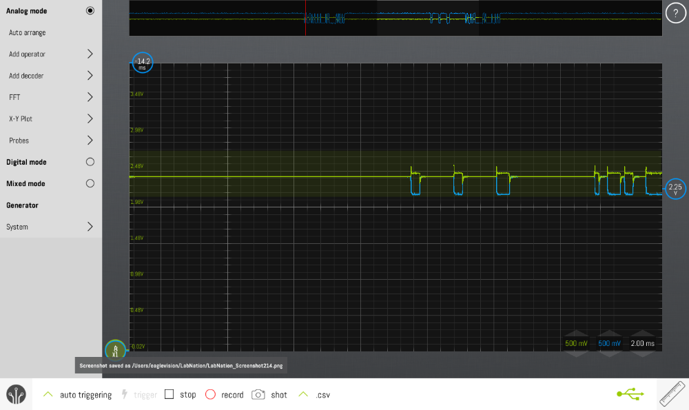
The good
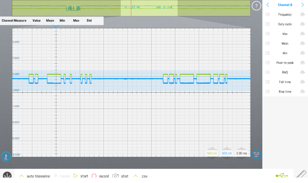
The bad
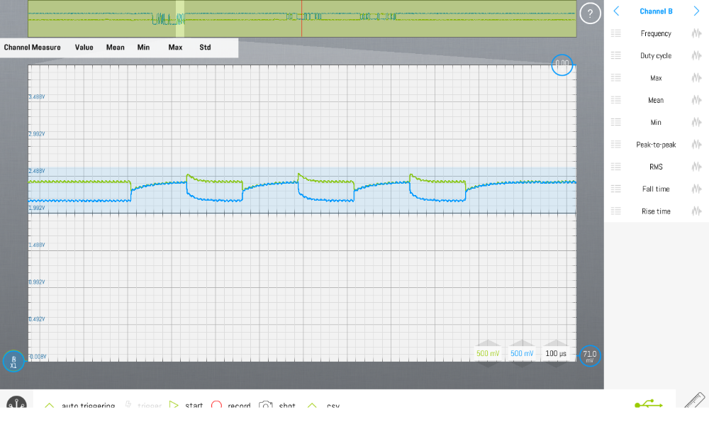
A close up of the bad
I'm assuming that all of the issues the vehicle has had are related to this bus issue.
Some waveforms on the bus are good but others are telling me a tale. I'm just not familiar enough with bad bus waveforms.
So many questions, but does this look like a bad PCM, bad module, power feed issue, ground issue, or something else?
As far as my Mitchell diagrams show, there are only 4 modules on the bus for this make model. I've disconnected the ABS and airbag and the bad waveform is still there,
so that really only leaves PCM and instrument cluster on the bus.
The good
The bad
A close up of the bad
Last edit: 3 years 11 months ago by Seanerz.
Please Log in or Create an account to join the conversation.
- jreardon
-
- Offline
- Platinum Member
-

Less
More
- Posts: 521
- Thank you received: 198
3 years 11 months ago #55417
by jreardon
Replied by jreardon on topic Help reading CCD Bus bad waveform - 2000 Dodge "No Bus"
Third picture: we have to remember that this is a differential bus. The signal on two separate channels looks wavy but the computer will take this noise out. Try 1 channel, 1 lead on bus - and the other lead on bus +.
The following user(s) said Thank You: Seanerz
Please Log in or Create an account to join the conversation.
- jreardon
-
- Offline
- Platinum Member
-
Less
More
- Posts: 521
- Thank you received: 198
3 years 11 months ago #55418
by jreardon
Replied by jreardon on topic Help reading CCD Bus bad waveform - 2000 Dodge "No Bus"
if this scope has math channel subtract channel 1 from channel 2
The following user(s) said Thank You: Seanerz
Please Log in or Create an account to join the conversation.
- Seanerz
-
Topic Author
- Offline
- New Member
-
Less
More
- Posts: 17
- Thank you received: 1
3 years 11 months ago #55423
by Seanerz
Replied by Seanerz on topic Help reading CCD Bus bad waveform - 2000 Dodge "No Bus"
Thanks y’all for reading. To be clear, I really want to know the CAUSE of the bad waveform here as I’m hoping it will point me in the direction of the diagnosis.
Why doesn’t look like the rest of good waves on the bus stream?
Why doesn’t look like the rest of good waves on the bus stream?
Please Log in or Create an account to join the conversation.
- jreardon
-
- Offline
- Platinum Member
-
Less
More
- Posts: 521
- Thank you received: 198
3 years 11 months ago #55442
by jreardon
Well the bus is not shorted one way or the other so must be bad transceiver.
My initial thought is to cut ccd+ and ccd- , wire in a replacement resistor and retake scope capture but that'll be too messy. How about taking out the fuse to one of them to shut it up. That will keep my wire cutting impulse at bay lol, plus that saves us from installing a resistor because the other terminating resistor will still be present on the bus. Then cycle the key and hope CCD bus will look either completely clean or completely bad. It will either be one or the other, then chase powers and grounds then?
Replied by jreardon on topic Help reading CCD Bus bad waveform - 2000 Dodge "No Bus"
that really only leaves PCM and instrument cluster on the bus
Well the bus is not shorted one way or the other so must be bad transceiver.
My initial thought is to cut ccd+ and ccd- , wire in a replacement resistor and retake scope capture but that'll be too messy. How about taking out the fuse to one of them to shut it up. That will keep my wire cutting impulse at bay lol, plus that saves us from installing a resistor because the other terminating resistor will still be present on the bus. Then cycle the key and hope CCD bus will look either completely clean or completely bad. It will either be one or the other, then chase powers and grounds then?
The following user(s) said Thank You: Seanerz
Please Log in or Create an account to join the conversation.
- Ben
-
- Offline
- Platinum Member
-
Less
More
- Posts: 1098
- Thank you received: 215
3 years 11 months ago #55475
by Ben
Replied by Ben on topic Re:Help reading CCD Bus bad waveform - 2000 Dodge "No Bus"
In my experience the no bus Message with a no start is the pcm is down either shorted 5v reference, lacking power or grounds, wiring issue between pcm and auto shutdown relay (possible corrosion in tipm) or a bad pcm
Sent from my SM-G781V using Tapatalk
Sent from my SM-G781V using Tapatalk
The following user(s) said Thank You: jreardon
Please Log in or Create an account to join the conversation.
- Matt T
-
- Offline
- Platinum Member
-
Less
More
- Posts: 751
- Thank you received: 276
3 years 11 months ago #55489
by Matt T
Replied by Matt T on topic Re:Help reading CCD Bus bad waveform - 2000 Dodge "No Bus"
Scan tool would be the better way to get some direction with this one. Offending module is likely to be the only no comm. May also be comm codes in some of the other modules. And FWIW PCM doesn't use CCD for diagnostics so if it won't talk to a scan tool go straight to it.
The following user(s) said Thank You: Seanerz, jreardon
Please Log in or Create an account to join the conversation.
- Seanerz
-
Topic Author
- Offline
- New Member
-
Less
More
- Posts: 17
- Thank you received: 1
3 years 11 months ago #55492
by Seanerz
Replied by Seanerz on topic Help reading CCD Bus bad waveform - 2000 Dodge "No Bus"
Thanks all! I was able to just unplug the PCM and scope the bus at the connector. The good waveform was still present but the bad wave was gone, so at this point I’m condemning the PCM.
That said, this is the second reman PCM ordered to replace the original (the first one also caused a "no bus"). So I'm having them send me a 3rd.
Weirdly, the original PCM ALSO has this bad waveform when connected, but the “No Bus” is intermittent, not happening all the time like the replacements.
What would cause all of the PCMs to have this glitch? Something’s definitely odd.
And to be sure, I’m reading good batt+ and 5v and grounds at the connectors, though I'm still doubting their integrity...
I wish I had a more professional scan tool or a DRBIII but I only have my scope and a Bluedriver scanner.
Hopefully the next PCM will be the silver bullet.
I’ll double check the ASD to PCM circuit too.
The following user(s) said Thank You: jreardon
Please Log in or Create an account to join the conversation.
Time to create page: 0.294 seconds