2004 Buick Lesabre CRANK Pos. Sensor strange voltage readings
- norbert.bartha
-
 Topic Author
- Offline
- New Member
-

- Posts: 6
- Thank you received: 0
The CKP sensor signal wires unplugged: 6V each, but once the sensor is plugged in, they drop to 1.68V and 0.68V and produce no signal. Voltage remains constant no matter what. Even when i turn the crank by hand. Problem started when i changed the CKP sensor to acdelco gold. It ran for 2 mins, then it just died and never started again. I did other work on it too so i could have messes something up but i dont know what and when. It was a front right motor mount replacement and intake manifold gasket.
I have tried 4 sensors and a new ICM. Same results, but on the new ICM, the ckp signal wires show 4.95V unplugged, meanwhile the old ICM sends 6V as I mentioned earlier. On a new gm genuine sensor, the voltages are 5.5V and 4.5V plugged in and it also does not produce a signal.
I know ICM is getting power and is sending power to ckp. But i am not sure about the ground. I measured the resistance between the sensor ground wire in the connector and the ICM ground location (g112) and block, chassis. Key off .First it was oily and it showed 8 ohms. I cleaned it and now its 3 ohms. Nothing else changed. No physical damage on wires. What should i check and how? I am running out of ideas. Thanm you!
Please Log in or Create an account to join the conversation.
- Tyler
-

- Offline
- Moderator
-

- Full time HACK since 2012
- Posts: 6115
- Thank you received: 1539
I have tried 4 sensors and a new ICM. Same results, but on the new ICM, the ckp signal wires show 4.95V unplugged, meanwhile the old ICM sends 6V as I mentioned earlier. On a new gm genuine sensor, the voltages are 5.5V and 4.5V plugged in and it also does not produce a signal.
That's interesting. :blink: I got curious about the variance in voltage on the sensor signal wires and dug around in service info. I found this in Crankshaft Position Sensor System Diagnosis:
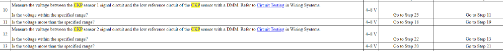
All your readings fall within the 4-8V range specified. So, IMO, your different signal voltages might be *A* problem but not *THE* problem.
The CKP sensor signal wires unplugged: 6V each, but once the sensor is plugged in, they drop to 1.68V and 0.68V and produce no signal. Voltage remains constant no matter what. Even when i turn the crank by hand.
The steady 1.68V and .68V are a big red flag for me. I'd suggest some voltage checks at the CKP first. All four pins, key on, sensor plugged in and unplugged. Here's a diagram of the CKP for reference:

Let us know what you find.

Please Log in or Create an account to join the conversation.
- Tyler
-
- Offline
- Moderator
-
- Full time HACK since 2012
- Posts: 6115
- Thank you received: 1539
Please Log in or Create an account to join the conversation.
- norbert.bartha
-
Topic Author
- Offline
- New Member
-
- Posts: 6
- Thank you received: 0
It ran for 2 minutes, then it just stopped as I heard a metallic sound, like a screw falling as the engine died.
I cant really imagine what's wrong. I will check ground wires around the pcm and starter if I can find them. Maybe something got loose as I was jacking up the engine for the motor mount change, buy i find it hard to believe. Maybe sensor ground? At this point I am just guessing

Please Log in or Create an account to join the conversation.
- norbert.bartha
-
Topic Author
- Offline
- New Member
-
- Posts: 6
- Thank you received: 0
Please Log in or Create an account to join the conversation.
- Tyler
-
- Offline
- Moderator
-
- Full time HACK since 2012
- Posts: 6115
- Thank you received: 1539
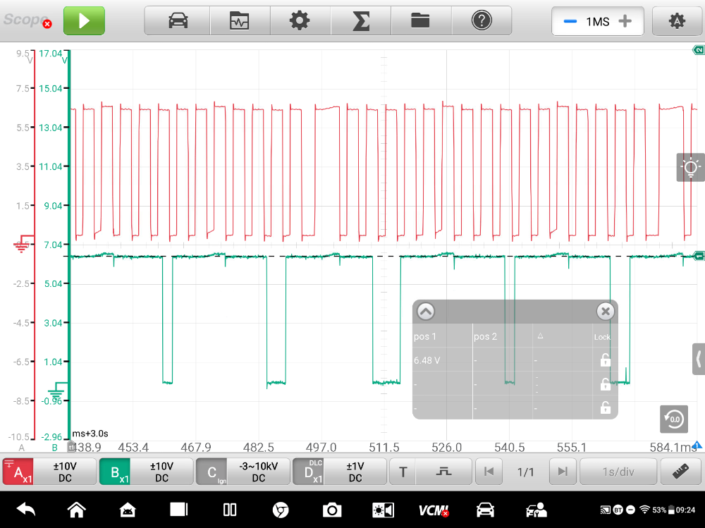
I thought its possible to measure the on-off signals with a multimeter when handcranking the engine.
It is. As the blades of the reluctor wheel pass in front of their sensors, the sensor signal should pull all the way to ground (or close to it). The fact that both signal wires stay low-ish regardless of reluctor position suggests the CKP sensor doesn't have something it needs to work correctly.
That's why you need to take voltage readings at all four wires at the CKP.
") Key on, all four wires with the sensor plugged in, and all four wires with the sensor unplugged.
Key on, all four wires with the sensor plugged in, and all four wires with the sensor unplugged. Please Log in or Create an account to join the conversation.
- Noah
-

- Offline
- Moderator
-
- Give code definitions with numbers!
- Posts: 5005
- Thank you received: 1116
"Ground cannot be checked with a 10mm socket"
Please Log in or Create an account to join the conversation.
- VegasJAK
-

- Offline
- Platinum Member
-

- Silencing the Parts Cannon
- Posts: 566
- Thank you received: 140
Learning from those with knowledge and wisdom. Thanks.
"an open mind let's knowledge flow in and wisdom flow out for a man who has neither never listens to those who have both".
Please Log in or Create an account to join the conversation.
- norbert.bartha
-
Topic Author
- Offline
- New Member
-
- Posts: 6
- Thank you received: 0
On Wednesday I when I get home I will check the ground properly and let you know what I found. Also I might try and experiment and just ground the sensors somewhere, leaving the ICM out and see if it creates the on-off signals... If this fails I am totally out of ideas.
Please Log in or Create an account to join the conversation.
- Tyler
-
- Offline
- Moderator
-
- Full time HACK since 2012
- Posts: 6115
- Thank you received: 1539
Teach me something here. If the ckp has 6v going in and 6v each going out on each signal wire unplugged and low voltage on each wire plugged in then the ground must be bad as it's constant?
I interpreted his opening post as having 6V on each signal wire, with no readings on the sensor power or ground. But I could have misinterpreted.
That's why I wanted to do some voltage checks - to make sure we're all on the same page, verify the sensor power/ground, AND check for other shenanigans (resistive shorts, replacement pigtails, like that).
Looking at the schematic the ground also goes to the cmp so wouldn't the cmp be effected as well?
If there is a ground problem, then definitely. We may circle back around to a CMP problem? For now, I'm focused on the CKP issue.
Please Log in or Create an account to join the conversation.
- VegasJAK
-
- Offline
- Platinum Member
-
- Silencing the Parts Cannon
- Posts: 566
- Thank you received: 140
I dislike generic diagrams. The ground switches shown for the cmp and ckp cannot work as shown. Has to have a coil to create a magnetic field to close the switches or transistors. I just have loads of problems with the design shown. I understand the hall effect design. Your engine has cam and crank sensors and reluctor rings to that end but the diagram to me is not representative of that design.
Listening and learning. Thanks
"an open mind let's knowledge flow in and wisdom flow out for a man who has neither never listens to those who have both".
Please Log in or Create an account to join the conversation.
- VegasJAK
-
- Offline
- Platinum Member
-
- Silencing the Parts Cannon
- Posts: 566
- Thank you received: 140
I know ICM is getting power and is sending power to ckp. But i am not sure about the ground.
He just didn't say what voltage reading.
Each signal wire has 6 voltages sent from the ecm.
"an open mind let's knowledge flow in and wisdom flow out for a man who has neither never listens to those who have both".
Please Log in or Create an account to join the conversation.
- norbert.bartha
-
Topic Author
- Offline
- New Member
-
- Posts: 6
- Thank you received: 0
")
Sorry if I was not very clear in my initial message. Let me clear it up. I tried a new ignition control module and both are getting power (12.7) and both are sending power to the ckp and cps. (11.5-12) so that number is somewhat lower.
I wonder where the ICM is getting power from? Is it through that large connector in front of the intake manifold, towards the fron of the car?
The 2 signal wires (18x , 3x) are showing 6V each when unplugged. With the new ICM they are 4.95V, very stable. With both ICM's when the sensor gets plugged in, this voltage drops to 1.68V in one wire and 0.68V in the other wire..
Does the same thing on 4 different sensors, except the new GM Genuine, because with that the voltage drops to 5.5v and 4.5V
Confusing, it is. Said Yoda
Tomorrow Ill be able to check the ground properly, because I only did resistance test while everything was unplugged. I am a just learning this stuff :S
Please Log in or Create an account to join the conversation.
- VegasJAK
-
- Offline
- Platinum Member
-
- Silencing the Parts Cannon
- Posts: 566
- Thank you received: 140
The 2 signal wires (18x , 3x) are showing 6V each when unplugged. With the new ICM they are 4.95V, very stable. With both ICM's when the sensor gets plugged in, this voltage drops to 1.68V in one wire and 0.68V in the other wire..
This is where I see the or a problem. Those signal wires while plugged in should be either 6v or 0v depending where the reluctor gates or windows are. Move the crank by hand. Do you get any different readings. Check the connection pins. Make sure no corrosion or female pins wider than normal causing a bad connection.
I have to say, ScannerDanner's forum is the best out there. Loaded with knowledgeable people willing to help those who need it. Just remember to keep posting until the problem is resolved so we can all learn from the experience.
"an open mind let's knowledge flow in and wisdom flow out for a man who has neither never listens to those who have both".
Please Log in or Create an account to join the conversation.
- norbert.bartha
-
Topic Author
- Offline
- New Member
-
- Posts: 6
- Thank you received: 0
black probe to battery negative
The sensor's ground wire showed 4.5mV (in one of the videos Paul said it has to be less then 1mV, so something like 0.008V is still ok. Do I remember correctly?)
Also the resistances are a little bit high too. 2-3.5 Ohm on average everywhere. I thought it should be close to 0. For example between sensor to block or battery, battery to block, block to chassis.
I tried an experiment with no luck. I cut the sensor's ground wire and grounded it to the block directly. Resistance of that ground was close to 0 ohms. Yet the sensor still acts like before. Nothing is changing.
I have a spare ignition switch. I will try it, maybe that is faulty and is messing with the electric system. I wish i could diagnose properly instead of throwing parts at is.
I think I'll buy the book here and read. Really confused by now
The machine spirit is mad
Next thing I will do: Jack the front up, and look around the starter motor for grounds, and look everywhere with a flashlight searching for bad grounds. Under the airbox is the PCM. I also read there are major grounds there too. Its lots of work, probably for nothing but I have no better idea.
Please Log in or Create an account to join the conversation.
- VegasJAK
-
- Offline
- Platinum Member
-
- Silencing the Parts Cannon
- Posts: 566
- Thank you received: 140
The sensor's ground wire showed 4.5mV (in one of the videos Paul said it has to be less then 1mV, so something like 0.008V is still ok. Do I remember correctly?)
Paul said less than 100mv (0.100v) so your 4.5mv is 0.0045v which is Ok.
"an open mind let's knowledge flow in and wisdom flow out for a man who has neither never listens to those who have both".
Please Log in or Create an account to join the conversation.
- VegasJAK
-
- Offline
- Platinum Member
-
- Silencing the Parts Cannon
- Posts: 566
- Thank you received: 140
Also the resistances are a little bit high too. 2-3.5 Ohm on average everywhere. I thought it should be close to 0. For example between sensor to block or battery, battery to block, block to chassis.
If you're trying to check for a short to ground on a wire using an ohm meter you have to isolate the wire you're testing. Connect one lead to the wire and the other lead to a body/block ground. You have to use the mega ohm scale. A good wire would be OLm ohms. That said the voltage test is the better test. The way you were doing it you were going through the entire circuit and picking up resistance from other components.
As Noah would say, Just smart enough to know I'm stupid.
"an open mind let's knowledge flow in and wisdom flow out for a man who has neither never listens to those who have both".
Please Log in or Create an account to join the conversation.
- Tyler
-
- Offline
- Moderator
-
- Full time HACK since 2012
- Posts: 6115
- Thank you received: 1539
The sensor's ground wire showed 4.5mV (in one of the videos Paul said it has to be less then 1mV, so something like 0.008V is still ok. Do I remember correctly?)
This was taken with the key on, backprobed at the CKP connector? If so, that reading is excellent.
") Paul's rule-of-thumb is 100mV or less. Your reading of 4.5mV is well within that.
Paul's rule-of-thumb is 100mV or less. Your reading of 4.5mV is well within that.Also the resistances are a little bit high too. 2-3.5 Ohm on average everywhere. I thought it should be close to 0. For example between sensor to block or battery, battery to block, block to chassis.
Like scannerjohn said, that's not a fantastic test. Some of that 2-3.5 Ohms could be in the multimeter leads. :silly:
For reference, I'm reposting the CKP wiring diagram:
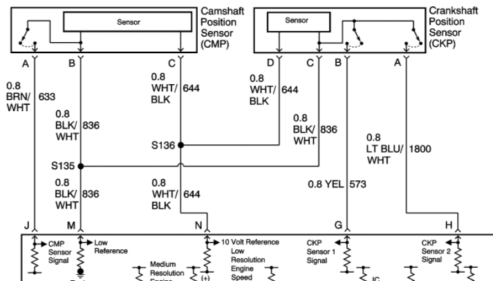
If we're gonna make a call on this, we need to be clear. What are you voltage readings on each pin at the CKP, sensor plugged in, key on and backprobed? A, B, C, D. Pin position and wire color matter.
If you truly have 6V on A and B, 10V on D and 4.5mV on C, then I'd argue that your latest sensor has failed. Electrically, it has everything it needs to work, and isn't. Pull the balancer and check carefully for coolant intrusion, physical damage, mounting, and reluctor issues like Noah mentioned.
Please Log in or Create an account to join the conversation.
- Tyler
-
- Offline
- Moderator
-
- Full time HACK since 2012
- Posts: 6115
- Thank you received: 1539
www.scannerdanner.com/scannerdanner-prem...se-study-part-1.html
Please Log in or Create an account to join the conversation.