2010 F250 6.4L no crank no start condition
- fahead32
-
 Topic Author
- Offline
- Junior Member
-

- Posts: 35
- Thank you received: 3
2- Connector 140 was disconnected to isolate the rest of the HS network leaving the PCM in circuit still no communication
If the scope is correct, where is that reading coming from if the PCM is faulty? Also there are some small spikes going in same direction and not opposite
I want to call the PCM but needed a second opinion
Please Log in or Create an account to join the conversation.
- Tyler
-

- Offline
- Moderator
-

- Full time HACK since 2012
- Posts: 6115
- Thank you received: 1539
Using the Verus D10 scope , the High speed Network ohmed at 112 ohm so a resistor was missing.
Where were you taking this measurement? At the DLC? Which pins were you probing, exactly?
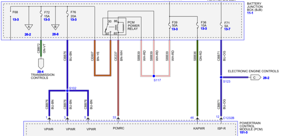
1- If the connector c1232 is removed the PCM the voltage disappears from fuse # 72- pin 1,3 and 5
You mean C1232B, correct? That makes sense, since it's the PCM that grounds the PCM Power Relay at pin 33 of C1232B. Without that ground, the PCM Power Relay won't close, and you'll lose power to fuse #68, 72 and 76:
2- Connector 140 was disconnected to isolate the rest of the HS network leaving the PCM in circuit still no communication
I (badly) smashed the two network pages together for reference:
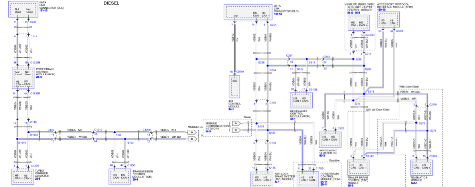
By my reading of the diagram, disconnecting C140 would have isolated the turbocharger actuator and the PCM from the DLC. :huh: I may not be understanding your test correctly.
If you measured 120 ohms between pins 6 and 14 of the DLC, then I'd suggest using C140 as a convenient way to break the circuit in two for testing purposes. Ohm the network in both directions to see where your open is. Or, stay connected at 6/14 and unplug C140. If the resistance stays at 120 ohms, your open is towards the PCM. If it goes infinite, your open is towards the Instrument Cluster.
Please Log in or Create an account to join the conversation.
- fahead32
-
Topic Author
- Offline
- Junior Member
-
- Posts: 35
- Thank you received: 3
Yes the dlc was my measuring point , also the reading remained when c140 was disconnected so would the PCM HS network need to be terminated to rule out PCM
Please Log in or Create an account to join the conversation.
- Tyler
-
- Offline
- Moderator
-
- Full time HACK since 2012
- Posts: 6115
- Thank you received: 1539
Yes the dlc was my measuring point
At pins 6/14? Sorry to harp on this, but it matters.
")
also the reading remained when c140 was disconnected so would the PCM HS network need to be terminated to rule out PCM
If you have a 120 ohm resistor available, you could connect it across pins 34 and 47 at C1232B to see if your resistance reading goes to 60 ohms and you get HS-CAN communication back. Or, disconnect C1232B and ohm across pins 34 and 47. Should measure 120 ohms.
Please Log in or Create an account to join the conversation.
- fahead32
-
Topic Author
- Offline
- Junior Member
-
- Posts: 35
- Thank you received: 3
Please Log in or Create an account to join the conversation.
- Tyler
-
- Offline
- Moderator
-
- Full time HACK since 2012
- Posts: 6115
- Thank you received: 1539
Use a break out box so I would have a conveinent spot have scanner wireless vci and can check pin 6 and 14
Gotcha, thank you.
")
Please Log in or Create an account to join the conversation.
- Tyler
-
- Offline
- Moderator
-
- Full time HACK since 2012
- Posts: 6115
- Thank you received: 1539

Please Log in or Create an account to join the conversation.
- fahead32
-
Topic Author
- Offline
- Junior Member
-
- Posts: 35
- Thank you received: 3
Please Log in or Create an account to join the conversation.
- fahead32
-
Topic Author
- Offline
- Junior Member
-
- Posts: 35
- Thank you received: 3
Please Log in or Create an account to join the conversation.
- Tyler
-
- Offline
- Moderator
-
- Full time HACK since 2012
- Posts: 6115
- Thank you received: 1539
Just read what you said carefully my problem seem to be with PCM then.
If you disconnect C1232B at the PCM and measure resistance across 34 and 47 on the PCM side, does it measure 120 ohms?
Quick question, do the PCM have both or only one terminating resistor? Still at the vehicle as you can guess
Only one. The other is in the Instrument Cluster.
Please Log in or Create an account to join the conversation.
- fahead32
-
Topic Author
- Offline
- Junior Member
-
- Posts: 35
- Thank you received: 3
After swallowing hard , I posted this to say nothing beats experience and you have to learn to check everything no matter how secure it looks
Thanks for all the help everyone
Please Log in or Create an account to join the conversation.
- Tyler
-
- Offline
- Moderator
-
- Full time HACK since 2012
- Posts: 6115
- Thank you received: 1539
Thank you. Please Log in or Create an account to join the conversation.