No crank no communication Dodge Stratus
- skins247
-
 Topic Author
- Offline
- New Member
-

- Posts: 12
- Thank you received: 0
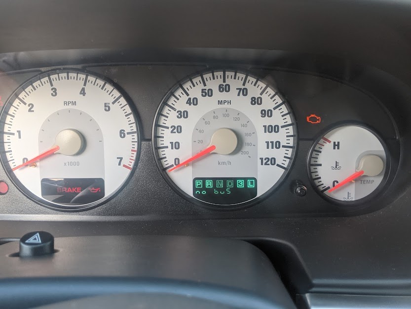
No Crank, No Comm....No bus code on dashboard....2006 Dodge Stratus 2.4 Automatic
Reportedly the car ran fine, although only used once or twice a week. Then the car started and stalled just after he last time it started...has been in crank , no communication state since....about 2 weeks....Good battery, and starter....all fuses checked and relays swapped here and there with same results...I checked for a 5v reference at the throttle position sensor, no 5v reference. I need to review some more SD videos before going further with unplugging sensors.....no wiring diagram as of yet, but I'll probably get one soon.... I've checked about for any obvious breaks in wires or corrosion , none that I saw.
The battery, although tested fine, and does not have a voltage drop outside the car....Does have what I was able to get as a .349 amps? draw on battery when vehicle is in sleep mode...everything closed etc...Haven't begun to find the circuit where the draw is yet...as it involves recharging the battery...and coordinating with my nephew to assist with the process....anyhow, thank you for any assistance in advance....much appreciated.
Please Log in or Create an account to join the conversation.
- Tyler
-

- Offline
- Moderator
-

- Full time HACK since 2012
- Posts: 6126
- Thank you received: 1542
Speaking of, I wanted to clarify. You stated this Stratus is no crank at one point, and cranking at another. Not trying to nitpick, just wanted to be clear.
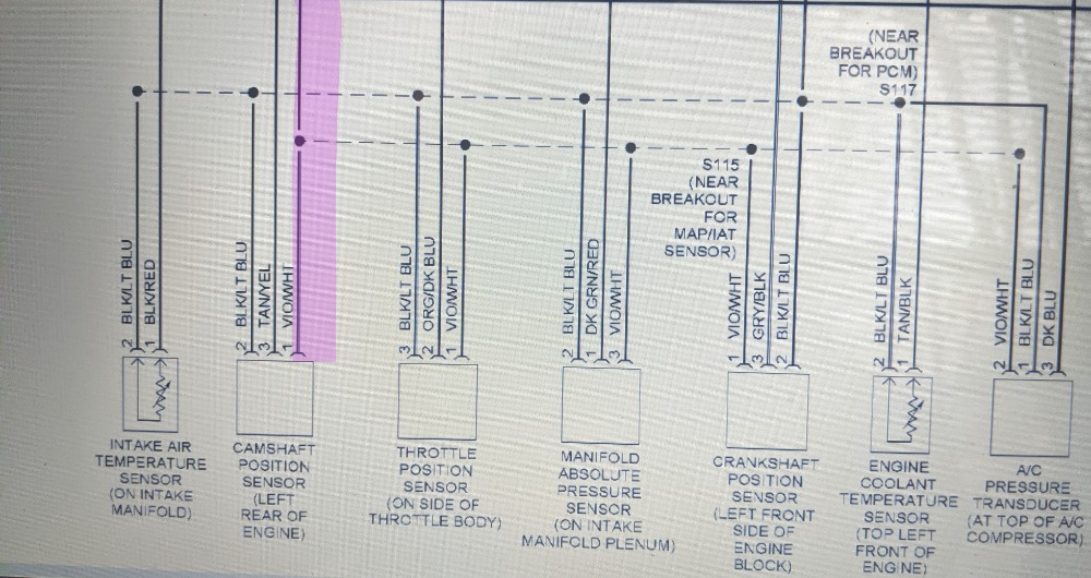
With the no comm and no 5V reference, I believe you're left with three possibilities. Shorted 5V reference, missing PCM power/ground, or failed PCM. Eliminating a shorted 5V would probably be the easiest first step, IMO. Find the violet/white wire at pin 29 of C2 at the PCM. That's the 5V feed for all the 5V reference sensors (CMP, CKP, MAP, TPS, A/C Pressure). Cut it close to the PCM, but not so close that you can't easily repair it later.
Power and ground is a little more work. You'll really need a wiring diagram for that. Mitchell DIY is an excellent option. Haynes is another. Both are very affordable compared to ProDemand or the like. Tons easier than sifting through one-make forums or Google Images to find the right diagram. :lol:
Please Log in or Create an account to join the conversation.
- skins247
-
Topic Author
- Offline
- New Member
-
- Posts: 12
- Thank you received: 0
Please Log in or Create an account to join the conversation.
- Tyler
-
- Offline
- Moderator
-
- Full time HACK since 2012
- Posts: 6126
- Thank you received: 1542
sorry to confuse....I was a little all over the place. It has not cranked since it stalled on him about 2 weeks ago. No issues prior to that incident, cranked and started consistently.
No worries, just wanted to make sure I understood.
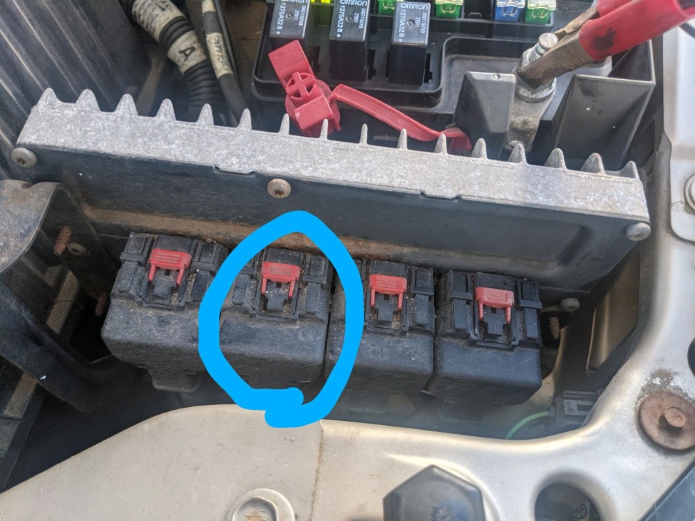
I appreciate your wealth of information, amazing. I'm struggling with ECM and PCM...In the picture is this the C2 of the PCM?...where is the ECM...
Dodge calls these PCM's because it's a Powertrain module. That (generally) means that this module controls the engine AND the transmission. There is no separate engine module and transmission module. It's all one brain box.
I believe that's C2? Service info indicates that C2 is orange in color. For reference, the sequence of connector colors should be black, orange, natural (white) and green. From there, pry that stupid wire cover off, YEET it, and find the violet/white wire.
and lastly upon cutting the wire and putting car in crank position, what will the lack of a "no bus" message being present indicate....and if it remains...that would indicate?
The logic is that, if the NO BUS message is no longer present with the 5V wire snipped, then the 5V reference was causing the PCM issue. Pursue a shorted 5V reference. If the NO BUS message remains, then the 5V reference circuit had nothing to do with it. It's not an elegant test, I know. :silly:
Be sure to cycle the key off for five or ten seconds between the cutting the wire and turning the key on again. Give the PCM a moment to power down and reset. No reason to go to Crank; key on will be good enough. The engine won't start without the CKP or CMP anyway.
If NO BUS remains, then we're checking PCM powers and grounds before calling a failed PCM.
Please Log in or Create an account to join the conversation.
- skins247
-
Topic Author
- Offline
- New Member
-
- Posts: 12
- Thank you received: 0
Please Log in or Create an account to join the conversation.
- skins247
-
Topic Author
- Offline
- New Member
-
- Posts: 12
- Thank you received: 0
Please Log in or Create an account to join the conversation.
- ontheriver
-
- Offline
- Premium Member
-

- Posts: 128
- Thank you received: 16
Please Log in or Create an account to join the conversation.
- skins247
-
Topic Author
- Offline
- New Member
-
- Posts: 12
- Thank you received: 0
Please Log in or Create an account to join the conversation.
- skins247
-
Topic Author
- Offline
- New Member
-
- Posts: 12
- Thank you received: 0
Please Log in or Create an account to join the conversation.
- Tyler
-
- Offline
- Moderator
-
- Full time HACK since 2012
- Posts: 6126
- Thank you received: 1542
If that doesn't restore communications, we're down to PCM powers, grounds and comm lines. If you get a hold of a wiring diagram, I can help you pick out which pins need to be tested.
Please Log in or Create an account to join the conversation.
- Tyler
-
- Offline
- Moderator
-
- Full time HACK since 2012
- Posts: 6126
- Thank you received: 1542
Please Log in or Create an account to join the conversation.
- skins247
-
Topic Author
- Offline
- New Member
-
- Posts: 12
- Thank you received: 0
Please Log in or Create an account to join the conversation.
- Chad
-

- Offline
- Moderator
-
- I am not a parts changer.
- Posts: 2196
- Thank you received: 738
If you get a hold of a wiring diagram, I can help you pick out which pins need to be tested.
")
"Knowledge is a weapon. Arm yourself, well, before going to do battle."
"Understanding a question is half an answer."
I have learned more by being wrong, than I have by being right.
Please Log in or Create an account to join the conversation.
- skins247
-
Topic Author
- Offline
- New Member
-
- Posts: 12
- Thank you received: 0
Please Log in or Create an account to join the conversation.
- Tyler
-
- Offline
- Moderator
-
- Full time HACK since 2012
- Posts: 6126
- Thank you received: 1542
any how if someone can let me know how much of a diagram , if any I can share on this forum for discussion purposes...or do I simply say C2 pin 29 vio/wht is listed as the 5v ref..and refer to wires that way,.....
Referring to connectors and pin numbers is the best way for others to follow along, IMO. Screenshots or snips of diagrams definitely help. Like this:
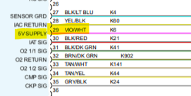
Windows Snipping Tool makes grabbing and highlighting diagrams a breeze.
support.microsoft.com/en-us/windows/use-...5f-f220-97299b865f6b
Please Log in or Create an account to join the conversation.
- skins247
-
Topic Author
- Offline
- New Member
-
- Posts: 12
- Thank you received: 0
Please Log in or Create an account to join the conversation.
- skins247
-
Topic Author
- Offline
- New Member
-
- Posts: 12
- Thank you received: 0
Please Log in or Create an account to join the conversation.
- Tyler
-
- Offline
- Moderator
-
- Full time HACK since 2012
- Posts: 6126
- Thank you received: 1542
Thank you...I'm trying to avoid cutting the 5v reference, if I'm able to access the sensors without a major problem...I'm wondering if there are many more than the ones shown on this snip it....the crank shaft one is a little tricky to get to and I haven't researched the a/c sensor location yet...just wondering how many more there might be.
Not to worry, that's all of them!
You can totally go for the individual sensors, too. Nothing wrong with that at all. I only made the wire cut suggestion because it provides a clear diagnostic yes/no path AND eliminates any possibility of a shorted 5V reference wire all at the same time. If you still have no 5V reference after disconnecting all those sensors, you'll still have to disconnect C2 of the PCM and ohm the 5V reference wire to ground to verify there is no wire short.
Please Log in or Create an account to join the conversation.
- skins247
-
Topic Author
- Offline
- New Member
-
- Posts: 12
- Thank you received: 0
Please Log in or Create an account to join the conversation.
- Cheryl
-
- Offline
- Platinum Member
-

- Posts: 1216
- Thank you received: 215
Please Log in or Create an account to join the conversation.