Help us help you. By posting the year, make, model and engine near the beginning of your help request, followed by the symptoms (no start, high idle, misfire etc.) Along with any prevalent Diagnostic Trouble Codes, aka DTCs, other forum members will be able to help you get to a solution more quickly and easily!
2010 Hyundai Elantra P0625 & P0626 - Alternator Woes
- Dtrujillo97
-
 Topic Author
- Offline
- New Member
-

Less
More
- Posts: 2
- Thank you received: 0
4 years 9 months ago #51113
by Dtrujillo97
2010 Hyundai Elantra P0625 & P0626 - Alternator Woes was created by Dtrujillo97
Hello all,
I’m working on a 2010 Hyundai Elantra with a 2.0L engine. The original complaint was MIL on with misfire codes and P0626 error code present, this error code changed to a P0625 during testing and now will not clear even by disconnecting battery terminals. The alternator has been replaced by another shop less than 1 year ago with a Mando unit (which is OEM I believe). The misfire codes were diagnosed as fouled spark plugs and is not my concern. To begin testing I checked alternator output voltage at idle and found it to be 14+ volts. I then unplugged alternator connector and found about 10V at signal wire which is correct according to Hyundai. I then scoped signal wire at alternator connector and found a 0-10V square wave style pattern at KOEO and KEOR at idle with no loads, and a flat line 0V with loads applied (blower motor and headlights on). Hyundai provides known good waveform samples in service manuals and they appear to all match according to each condition. I then moved closer to PCM and performed the same test by piercing signal wire about 3 inches above PCM and received same signals. I then decided to remove PCM connector cover to perform a back-probe test at PCM connector and this is where I got stumped. If back-probed at PCM I have a constant 12V-14V, so essentially battery voltage, no switching of the signal. I performed resistance and continuity test of wire from ALT to PCM and had resistance of about 1 OHM and continuity.
My questions are this: 1.) Why do I now have a low circuit code that will not clear if I have a constant 12-14V? I believe that should produce the original code the vehicle came in for which is a P0626 (high circuit code generator F terminal). 2.) Why when back-probed at PCM connector do I have a constant signal and not switching?
Testing was performed using a Fluke Multimeter and Snap-On Verus Pro 4-Channel lab scope. Ground lead for scope was constantly connected to negative terminal at battery.
Thanks in advance")
I’m working on a 2010 Hyundai Elantra with a 2.0L engine. The original complaint was MIL on with misfire codes and P0626 error code present, this error code changed to a P0625 during testing and now will not clear even by disconnecting battery terminals. The alternator has been replaced by another shop less than 1 year ago with a Mando unit (which is OEM I believe). The misfire codes were diagnosed as fouled spark plugs and is not my concern. To begin testing I checked alternator output voltage at idle and found it to be 14+ volts. I then unplugged alternator connector and found about 10V at signal wire which is correct according to Hyundai. I then scoped signal wire at alternator connector and found a 0-10V square wave style pattern at KOEO and KEOR at idle with no loads, and a flat line 0V with loads applied (blower motor and headlights on). Hyundai provides known good waveform samples in service manuals and they appear to all match according to each condition. I then moved closer to PCM and performed the same test by piercing signal wire about 3 inches above PCM and received same signals. I then decided to remove PCM connector cover to perform a back-probe test at PCM connector and this is where I got stumped. If back-probed at PCM I have a constant 12V-14V, so essentially battery voltage, no switching of the signal. I performed resistance and continuity test of wire from ALT to PCM and had resistance of about 1 OHM and continuity.
My questions are this: 1.) Why do I now have a low circuit code that will not clear if I have a constant 12-14V? I believe that should produce the original code the vehicle came in for which is a P0626 (high circuit code generator F terminal). 2.) Why when back-probed at PCM connector do I have a constant signal and not switching?
Testing was performed using a Fluke Multimeter and Snap-On Verus Pro 4-Channel lab scope. Ground lead for scope was constantly connected to negative terminal at battery.
Thanks in advance
Please Log in or Create an account to join the conversation.
- VegasJAK
-

- Offline
- Platinum Member
-

- Silencing the Parts Cannon
Less
More
- Posts: 566
- Thank you received: 140
4 years 9 months ago #51130
by VegasJAK
"an open mind let's knowledge flow in and wisdom flow out for a man who has neither never listens to those who have both".
Replied by VegasJAK on topic 2010 Hyundai Elantra P0625 & P0626 - Alternator Woes
Did you reposition your probe and still get the 12/14v.
On another post, they guy did the same thing on his Nissan. He repositioned his probe and got his square wave at the pcm.
On another post, they guy did the same thing on his Nissan. He repositioned his probe and got his square wave at the pcm.
"an open mind let's knowledge flow in and wisdom flow out for a man who has neither never listens to those who have both".
Being wrong doesn't bother me, it's being right and not understanding why that does
Please Log in or Create an account to join the conversation.
- Dtrujillo97
-
Topic Author
- Offline
- New Member
-
Less
More
- Posts: 2
- Thank you received: 0
4 years 9 months ago #51138
by Dtrujillo97
Replied by Dtrujillo97 on topic 2010 Hyundai Elantra P0625 & P0626 - Alternator Woes
Hi John,
Yes I did reposition probe numerous times, results were always the same though.
Yes I did reposition probe numerous times, results were always the same though.
Please Log in or Create an account to join the conversation.
- Tyler
-

- Offline
- Moderator
-

- Full time HACK since 2012
Less
More
- Posts: 6126
- Thank you received: 1542
4 years 9 months ago #51148
by Tyler
If I'm reading service info correctly, then the code isn't describing a low voltage problem, but a low duty cycle problem. "ECM sets DTC P0625 if the ECM detects output duty cycle lower than the possible range of a properly functioning alternator." Here's the code set criteria:
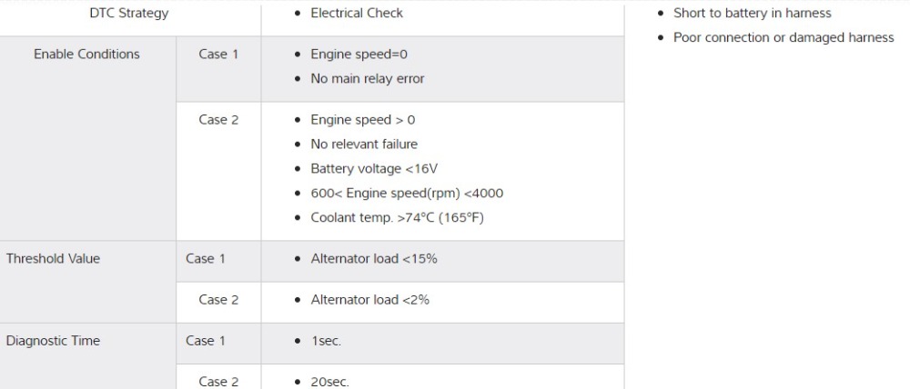
This suggests to me that the steady 12-14V you saw while backprobing is what the ECM is upset about. It's seeing zero duty cycle, when it knows it shouldn't.
Why did you see a duty cycle 3" away from the ECM, but no signal while backprobing? Good question. :silly: Are you confident that you weren't crossed into another pin with your backprobe? I'd be tempted to watch the signal voltage 3" away and the backprobe at the same time.
It might also be good to disconnect the ECM connector and do your continuity testing on the front of the pin. Gently, of course. It's possible you're fighting a poorly crimped pin or corrosion inside the connector itself.
Replied by Tyler on topic 2010 Hyundai Elantra P0625 & P0626 - Alternator Woes
1.) Why do I now have a low circuit code that will not clear if I have a constant 12-14V? I believe that should produce the original code the vehicle came in for which is a P0626 (high circuit code generator F terminal).
If I'm reading service info correctly, then the code isn't describing a low voltage problem, but a low duty cycle problem. "ECM sets DTC P0625 if the ECM detects output duty cycle lower than the possible range of a properly functioning alternator." Here's the code set criteria:
This suggests to me that the steady 12-14V you saw while backprobing is what the ECM is upset about. It's seeing zero duty cycle, when it knows it shouldn't.
Why did you see a duty cycle 3" away from the ECM, but no signal while backprobing? Good question. :silly: Are you confident that you weren't crossed into another pin with your backprobe? I'd be tempted to watch the signal voltage 3" away and the backprobe at the same time.
It might also be good to disconnect the ECM connector and do your continuity testing on the front of the pin. Gently, of course. It's possible you're fighting a poorly crimped pin or corrosion inside the connector itself.
Please Log in or Create an account to join the conversation.
Time to create page: 0.284 seconds