2011 Mini Countryman
- Richard1
-
 Topic Author
- Offline
- Junior Member
-

- Posts: 20
- Thank you received: 0
1.6 L engine
I get this code: P3016 on my scanner:
"Internal control module O2 sensor calibration resistance error bank1 sensor1"
This sensor was replaced but not an OEM
Average fuel used excellente 7L/100km
Both trim codes near 0
NO CHECK ENGINE LIGHT
no missfire.
If I clear the scanner error code it returns in a few minutes.
I'm out of ideas, anyone's help appreciated.
Richard
Please Log in or Create an account to join the conversation.
- guafa
-
- Offline
- Platinum Member
-

- Posts: 477
- Thank you received: 80
Is downstream sensor same as upstream?
If it is, i would swap them to confirm whether or not code moves.
Please Log in or Create an account to join the conversation.
- Richard1
-
Topic Author
- Offline
- Junior Member
-
- Posts: 20
- Thank you received: 0
That was a good thought, but there not the same, and it does go into closed loop go figure.
Please Log in or Create an account to join the conversation.
- guafa
-
- Offline
- Platinum Member
-
- Posts: 477
- Thank you received: 80
I don't know the circuit you are dealing with. I only can imaging an internal voltage divider circuit which is being affected by the resistance of this new no oem sensor.
Do they have the same resistance (old and new)?
Please Log in or Create an account to join the conversation.
- Richard1
-
Topic Author
- Offline
- Junior Member
-
- Posts: 20
- Thank you received: 0
Unfortunately I did not keep the old one but its a 4 wire so probably a heated one and I believe those cannot be tested with a multimeter for resistance.
Wish I had access to AllData or Identafix to see the wiring diagram for this mini.
But thank you
Please Log in or Create an account to join the conversation.
- guafa
-
- Offline
- Platinum Member
-
- Posts: 477
- Thank you received: 80
Please Log in or Create an account to join the conversation.
- Richard1
-
Topic Author
- Offline
- Junior Member
-
- Posts: 20
- Thank you received: 0
Model R60
1.6L non turbo
Vin: WMWZB3102BWL00329
Please Log in or Create an account to join the conversation.
- guafa
-
- Offline
- Platinum Member
-
- Posts: 477
- Thank you received: 80
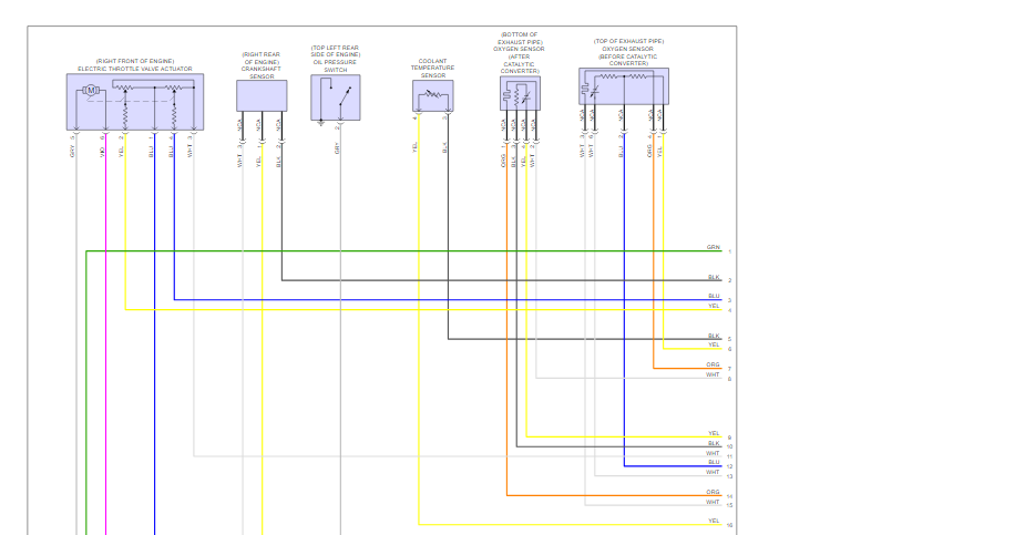
I´m confused, since you mentioned sensor 1 is a 4 wire. Drawings are suggesting sensor 1 is a 5 wire one. Is it at top of exhaust pipe?
Please Log in or Create an account to join the conversation.
- Richard1
-
Topic Author
- Offline
- Junior Member
-
- Posts: 20
- Thank you received: 0
Possibly the downstream had 4
Thenk you
Please Log in or Create an account to join the conversation.
- guafa
-
- Offline
- Platinum Member
-
- Posts: 477
- Thank you received: 80
My first interpretation is that sensor signal (gray) has a voltage reference (blue) and a ground reference (yellow). They are reference voltage PCM expects to read (sense) and depend on values of internal sensor voltage divider (internal resistance).
So my first shoot would be to compare those resistance with oem sensor (i know you trashed it). We need to find some kind of test procedure which let us know those resistance values.
Why did you change oem sensor by the way?
Please Log in or Create an account to join the conversation.
- Richard1
-
Topic Author
- Offline
- Junior Member
-
- Posts: 20
- Thank you received: 0
After both sensors were changed it now goes well into closed loop without the check engine, but on the scanner I still get the P3016 with no other adverse effect. Would i not have a scanner, I would have no way to know there is still something not quite right.
I'm surprised that everything else is in order fuel trims are great below 3% combined.
Is it worth continuing the research I believe it is, even if only for the knowledge gained on after market parts which like you I'm tempted to believe the new sensor internal resistance when in operation can be different, but i was under the impression the this type of sensor can only be verified by looking at the miliamps on a scope?
I could be wrong, would not be the first time lol.
Please Log in or Create an account to join the conversation.
- Richard1
-
Topic Author
- Offline
- Junior Member
-
- Posts: 20
- Thank you received: 0
Does the sensor page give any type of reference voltages on that sensor connector or a standard waveform to compare to?
Please Log in or Create an account to join the conversation.
- guafa
-
- Offline
- Platinum Member
-
- Posts: 477
- Thank you received: 80
P3016 is related to a calibration resistance inside pcm, which determines heater temperature (not related to signal circuit).
It is set due to pcm expects to read a voltage (inside pcm) when a voltage is aplied to that calibration resistance.
That seems if you have tested pcm voltages and grounds and they are correct, you have a pcm issue.
Please Log in or Create an account to join the conversation.
- Richard1
-
Topic Author
- Offline
- Junior Member
-
- Posts: 20
- Thank you received: 0
Thank you for your patience, I would test the PCM voltages for sure but I do not know what the specs. should be, if you have that info I would appreciate it.
Today the engine stayed in open loop till I turned it off and started it again, but still no check engine, just the P3016 on the scanner.
It would be easy for me to backprobe it, easy access.
Please Log in or Create an account to join the conversation.
- guafa
-
- Offline
- Platinum Member
-
- Posts: 477
- Thank you received: 80
You shouldn't see more than 100mV on grounds and battery voltage drops on power wires.
PCM has decided to stay in open loop because she detected a problem which doesn't allow to see O2 sensor accurately.
The fact MIL is not ON could be is waiting for a certain amount of cycles or the code is categorized as "soft code"
Bear in mind also that i don't know how that calibration resistance is conected to O2 sensor heater, then i don't know whether or not your new non oem O2 sensor heater is affecting the calibration process.
Please Log in or Create an account to join the conversation.
- Richard1
-
Topic Author
- Offline
- Junior Member
-
- Posts: 20
- Thank you received: 0
Thank you
Please Log in or Create an account to join the conversation.
- Richard1
-
Topic Author
- Offline
- Junior Member
-
- Posts: 20
- Thank you received: 0
Please Log in or Create an account to join the conversation.
- Richard1
-
Topic Author
- Offline
- Junior Member
-
- Posts: 20
- Thank you received: 0
Please Log in or Create an account to join the conversation.