Help us help you. By posting the year, make, model and engine near the beginning of your help request, followed by the symptoms (no start, high idle, misfire etc.) Along with any prevalent Diagnostic Trouble Codes, aka DTCs, other forum members will be able to help you get to a solution more quickly and easily!
Chevy 350 intake vacuum waveform
- guafa
-
 Topic Author
- Offline
- Platinum Member
-

Less
More
- Posts: 477
- Thank you received: 80
4 years 7 months ago #50997
by guafa
Chevy 350 intake vacuum waveform was created by guafa
Hello guys,
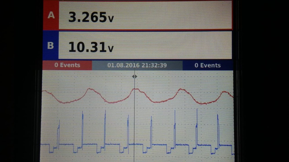
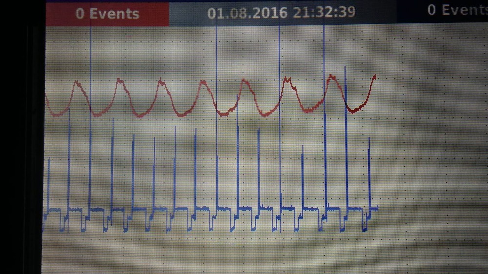
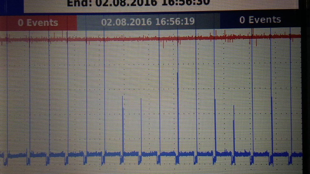
Blue trace is primary ignition coil in a distributor type and red trace is intake vacuum.
This engine has modified camshatf (a little overlaping according to customer)
Vacuum idle (cold) is about 6.5 in/Hg and (warm) about 9.5 in/Hg.
My question is how modified camshaft could affect vacuum waveform, since I am watching just one valley every two ignition pulses instead of two valleys (all cylinders sucking separatedly).
Any comment would be apreciated.
Please Log in or Create an account to join the conversation.
- Hardtopdr2
-
- Offline
- Platinum Member
-
Less
More
- Posts: 853
- Thank you received: 150
4 years 7 months ago #51010
by Hardtopdr2
Replied by Hardtopdr2 on topic Chevy 350 intake vacuum waveform
with a normal aka stock camshaft the lobe separation angle is a bit more separated so the exhaust valve closes before intake valve opens. Now on a modified camshaft aka high performance drag strip cam that separation angle is moved as power is the primary desire (not engine vacuum or idle quality) which is why the drag cars and high compression engines have the lope to it when its started. with this move of the separation angle your power band with the camshaft is moved to the upper rpm ranges or vise versa depending on which way you go.
as for the waveform did you take it with the engine running or just cranking?
as for the waveform did you take it with the engine running or just cranking?
Please Log in or Create an account to join the conversation.
- guafa
-
Topic Author
- Offline
- Platinum Member
-
Less
More
- Posts: 477
- Thank you received: 80
4 years 7 months ago #51018
by guafa
Replied by guafa on topic Chevy 350 intake vacuum waveform
Thanks hardtopdr2 for your prompt response.
Capture was taken at idle.
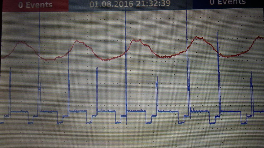
Another picture a took before, was secondary ignition on cylinder #1 (blue) and vacuum (red) at idle (see attached file). I could notice cylinders 1, 4, 6 and 7 are the ones which generate that valleys. On the other hand 8, 3, 5 and 2 match the peaks (which are the ones i would expect to generate another valleys)
Due to not all the valleys or peaks are being generated on the same bank, and also the fact that every peak is followed by a valley (so symetrical waveform) i would discard a mechanical issue)
I am definitely not familiarized with modified camshaft, but my common sense doesn't explain why i am not seeing the intake job (valleys) for every cylinder (since camshaf overlaping is aplying to all cylinders and intake stroke is 90 degress separated one from another)
Capture was taken at idle.
Another picture a took before, was secondary ignition on cylinder #1 (blue) and vacuum (red) at idle (see attached file). I could notice cylinders 1, 4, 6 and 7 are the ones which generate that valleys. On the other hand 8, 3, 5 and 2 match the peaks (which are the ones i would expect to generate another valleys)
Due to not all the valleys or peaks are being generated on the same bank, and also the fact that every peak is followed by a valley (so symetrical waveform) i would discard a mechanical issue)
I am definitely not familiarized with modified camshaft, but my common sense doesn't explain why i am not seeing the intake job (valleys) for every cylinder (since camshaf overlaping is aplying to all cylinders and intake stroke is 90 degress separated one from another)
Please Log in or Create an account to join the conversation.
- juergen.scholl
-

- Offline
- Platinum Member
-
- Active partschanger
Less
More
- Posts: 1233
- Thank you received: 462
4 years 7 months ago #51019
by juergen.scholl
An expert is someone who knows each time more on each time less, until he finally knows absolutely everything about absolutely nothing.
Replied by juergen.scholl on topic Chevy 350 intake vacuum waveform
Do you have an intake vacuum waveform while cranking?
An expert is someone who knows each time more on each time less, until he finally knows absolutely everything about absolutely nothing.
Please Log in or Create an account to join the conversation.
- guafa
-
Topic Author
- Offline
- Platinum Member
-
Less
More
- Posts: 477
- Thank you received: 80
4 years 7 months ago #51020
by guafa
Replied by guafa on topic Chevy 350 intake vacuum waveform
juergen.scholl.
Just give me a couple of hours and i'll post it.
Thanks in advance.
Just give me a couple of hours and i'll post it.
Thanks in advance.
Please Log in or Create an account to join the conversation.
- Matt T
-
- Offline
- Platinum Member
-
Less
More
- Posts: 751
- Thank you received: 276
4 years 7 months ago #51023
by Matt T
Replied by Matt T on topic Chevy 350 intake vacuum waveform
There's a good chance 1, 4, 6 & 7 are tied together as one half of a dual plane intake. You might have your transducer hooked to a port that only sees one of the intake planes. Or there could be a restriction in one of the planes.Another picture a took before, was secondary ignition on cylinder #1 (blue) and vacuum (red) at idle (see attached file). I could notice cylinders 1, 4, 6 and 7 are the ones which generate that valleys. On the other hand 8, 3, 5 and 2 match the peaks (which are the ones i would expect to generate another valleys)
Due to not all the valleys or peaks are being generated on the same bank, and also the fact that every peak is followed by a valley (so symetrical waveform) i would discard a mechanical issue)
Please Log in or Create an account to join the conversation.
- guafa
-
Topic Author
- Offline
- Platinum Member
-
Less
More
- Posts: 477
- Thank you received: 80
4 years 7 months ago #51024
by guafa
Replied by guafa on topic Chevy 350 intake vacuum waveform
Ok guys.
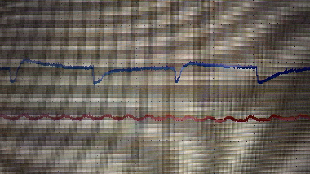
Here is a picture of vacuum while cranking.
Map voltage (red trace) is 3.9v (which is barometric pressure here (82 kpa)). As you can see there is no vacuum pressure.
Matt T. All readings were taken at throttle body ( 400 hp 4 barrel fi tech) system.
Intake manifold is eldelbrock 2101 (i know nothing about this intake manifold but i'm afraid it doesn't have any test port)
Please Log in or Create an account to join the conversation.
- Matt T
-
- Offline
- Platinum Member
-
Less
More
- Posts: 751
- Thank you received: 276
4 years 7 months ago #51028
by Matt T
Replied by Matt T on topic Chevy 350 intake vacuum waveform
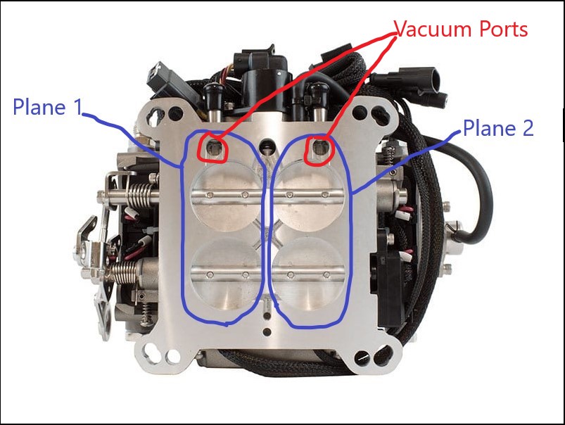
It is a dual plane intake. And it sure looks like the vacuum ports on that throttle body could isolated from one plane somewhat. One thing you could try is moving the transducer to another port to see if that shows the other four intake pulls.Matt T. All readings were taken at throttle body ( 400 hp 4 barrel fi tech) system.
Intake manifold is eldelbrock 2101 (i know nothing about this intake manifold but i'm afraid it doesn't have any test port)
The following user(s) said Thank You: juergen.scholl, Chad
Please Log in or Create an account to join the conversation.
- guafa
-
Topic Author
- Offline
- Platinum Member
-
Less
More
- Posts: 477
- Thank you received: 80
4 years 7 months ago #51064
by guafa
Replied by guafa on topic Chevy 350 intake vacuum waveform
Matt T mate you are genious!!!
I confirm by watching through throttle body blades that intake has two separated paths. One for cylinders 1,4,6,7 and the other for 8,3,5,2
You saved me lots of hours. That must be the reason for that waveform.
I confirm by watching through throttle body blades that intake has two separated paths. One for cylinders 1,4,6,7 and the other for 8,3,5,2
You saved me lots of hours. That must be the reason for that waveform.
Please Log in or Create an account to join the conversation.
Time to create page: 0.373 seconds