2010 chevey equinox 2.4 L, no crank, no start, U0100 P0615 P1682
- stspringer
-
 Topic Author
- Offline
- New Member
-

- Posts: 17
- Thank you received: 2
I am not a mechanic, just a learning enthusiast. For a learning experiment, I removed the starter relay from my underhood fusebox, and with the key in the on position, I jumped terminal 30 to terminal 87, and as expected the car started.
Then a few days later I mistakenly jumped terminal 30 to terminal 86. Terminal 30 is always hot, terminal 86 is ground. I created a short! I saw smoke come out of the fusebox.
These are codes I got when I was able to communicate.
U0100 lost communication with an engine control module
P0615 starter relay control circuit
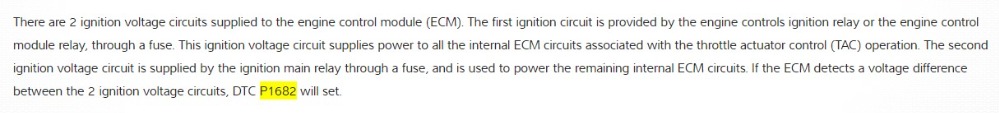
P1682 Ignition 1 switch circuit 2
So now I can still start the car by jumping from terminal 30 to terminal 87, and the car runs, but I can NOT start the car with the key in the start position.
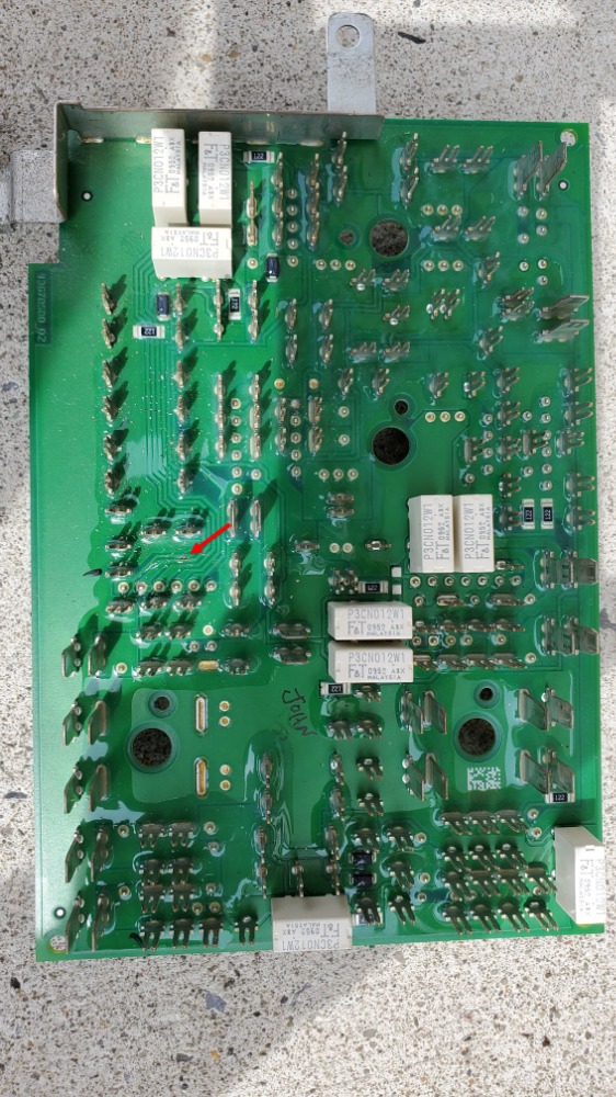
I took apart the fuse box and I can see a burnt trace on the circuit board. I purchased a used 2010 equinox fuse box on eBay put it in and got crazy instrument lights etc found out it must be programmed. I am in the process of checking out how to get it programmed. This eBay fuse box also had a broken 80 amp fuse connection that was broken I contacted the seller and he told me to keep the fuse box and he will refund my $43.00 dollars, and so I kept the fuse box with all the fuses and relays, and the seller did refund my money. Nice
Here are the tests I ran so far
Sunday 06_27_2021 using the power probe 3
I put the bad fuse box circuit board, with the "burnt trace" in the eBay fuse box housing case, with no 80A fuse because the fuse connectors are broken off on this eBay fuse box case. I then removed the starter relay and with the key in the on position, I jumped the starter relay base terminal 30 to terminal 87. The car started and kept running with instrument lights on and no check engine light. I then turned the key to the off position and then turned the key to the start position and I have no instrument lights and the check engine light is on.
Further testing with the power probe 3
Key off
using a relay jumper with the starter relay plugged into the relay jumper, terminal 30 reads 12.6v with the red led lit, terminal 87 reads zero v with the green led lit, terminal 85, which is the positive control side to the starter relay coil, reads zero v and the green led is lit, terminal 86 , which is the negative control side to the starter relay coil, reads zero v and the green led is lit.
Key on
using a relay jumper with the starter relay plugged into the relay jumper, terminal 30 reads 12.6v with the red led lit, terminal 87 reads zero v with the green led lit, terminal 85, which is the positive control side to the starter relay coil, reads zero v and the green led is lit, terminal 86 , which is the negative control side to the starter relay coil, reads zero v and the green led is lit.
Key in the start position
using a relay jumper with the starter relay plugged into the relay jumper, terminal 30 reads 12.4v with the red led lit, terminal 87 reads zero v with the green led lit, terminal 85, which is the positive control side to the starter relay coil, reads 2.4 v and no led's are lit on the power probe, terminal 86 , which is the negative control side to the starter relay coil, reads zero v and the green led is lit.
Conclusion
I have a 10.2v voltage drop on terminal 85, which is the positive control side to the starter relay coil, with the key in the start position, I have no instrument lights and the check engine light is on.
So please advise should I put in a programmed circuit board into the fusebox, or should I check other sensors first, or what?
Thanks for any help
Please Log in or Create an account to join the conversation.
- Tyler
-

- Offline
- Moderator
-

- Full time HACK since 2012
- Posts: 6126
- Thank you received: 1542
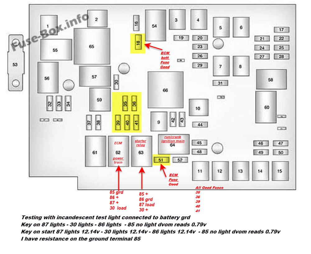
I'd stay with the positive side of the starter relay for now. Install your relay jumper WITHOUT the relay and check terminal 85 with an incandescent test light connected to B- with the key in crank. Does it light? If yes, swap a different relay in and retest.
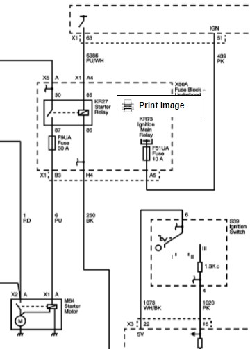
If no, unclip the fuse box from its carrier and flip it over (if possible). Connector X1, terminal A4:
Again, test light to B-, see if A4 lights up. If yes, there's high resistance between terminal A4 and terminal 85 in the fuse box. If no, we're headed towards the ECM. You can use your PP3 for these tests, but an incandescent test light really would be better.
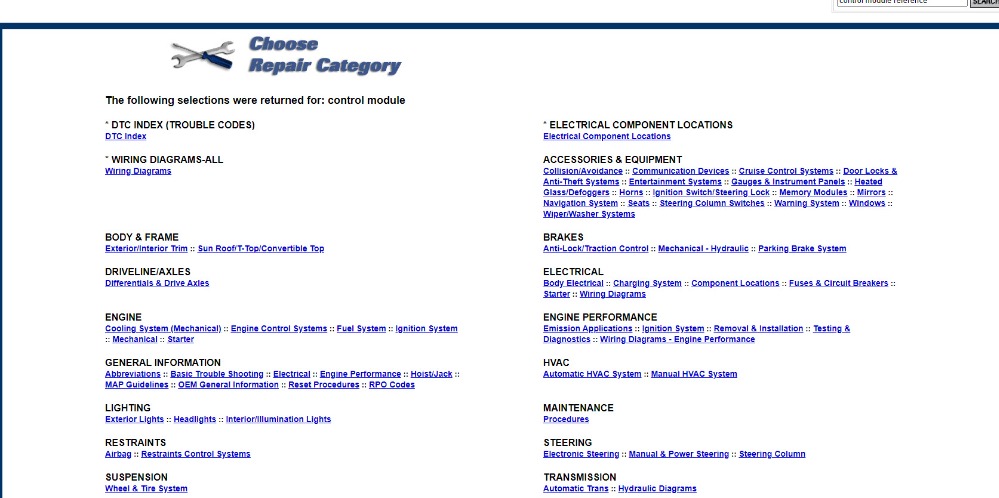
No offense meant, but are you positive that the X50A Underhood Fuse Box has to be programmed? Because I looked it up in the Control Module Reference - X50A isn't on it.
Please Log in or Create an account to join the conversation.
- stspringer
-
Topic Author
- Offline
- New Member
-
- Posts: 17
- Thank you received: 2
I will try your suggestions, and tell you what I find.
"No offense meant, but are you positive that the X50A Underhood Fuse Box has to be programmed? Because I looked it up in the Control Module Reference - X50A isn't on it."
I was told by some mechanic the fuse box had to be programmed and also the eBay guy asked me if I programmed the fuse box, so I thought this fuse box had to be programmed.
I have Mitchelle1 with a 1-year subscription. Can you tell me how to find the "Control Module Reference - X50A" in Mitchell1. in regards to how to determine if programming is necessary, I find navigating in Mitxhell1 is not really easy for a novice.
Also Just out of curiosity, what are the odds that my trouble codes could be just from the burnt trace on the circuit board? Thanks
Please Log in or Create an account to join the conversation.
- stspringer
-
Topic Author
- Offline
- New Member
-
- Posts: 17
- Thank you received: 2
Well, I did the tests you suggested. I had a heck of a time getting to A4 by flipping the fuse box but I did finally get to A4 with a T-pin.
The wire is purple and white, I did not get my test light to light in either test, so you say we are now pointing to the ECM.
Question:
I did use the relay jumper "without the relay" on the first test, but on the second test for A4 I had the relay plugged in, "brain fart" Is that a game-breaker? If so I will run the test again when I have an assistant handy to crank the engine.
The car still starts and runs with no check engine light, when I jump terminal 30 to 87
I will now study your videos for checking the ECM for power and ground.
Any more advice from here forward is appreciated.
Thank You,
Please Log in or Create an account to join the conversation.
- Tyler
-
- Offline
- Moderator
-
- Full time HACK since 2012
- Posts: 6126
- Thank you received: 1542
Search Mitchell1 for Control Module Reference. It's the document you refer to if you're performing a module replacement, or considering one. If it requires programming, what relearns/resets are required, like that. If the part you're replacing isn't on it, you're good to go. There are also entries on there that say, '_______ module doesn't require programming'.
The burned trace may be related? But I'm not there yet. IMO, when you shorted 30 to 86, you should have cooked the ground trace through the board, and potentially anything down the line. 85 is a separate circuit, and *shouldn't* have been damaged.
That's what testing at pin A4 is for - to determine if the fuse box damage is stopping 12V from making it to the relay. Testing there skips over the box and just leaves the wiring, connections and PCM.
I suggested leaving the relay out in the off chance that the relay coil and/or fuse box is shorted, and causing the PCM driver to struggle. This is a high side driver, so it really shouldn't behave that way? I just wanted to ensure the PCM had every chance to work correctly.
If you wanted to assure yourself that the burned trace isn't at fault, you can use your PP3 to jump 12V to pin A4, relay installed. If the engine cranks, then all connections to that point are good (or good enough, anyway). You can also use an incandescent test light in the same way, if you're nervous about jumping stuff.
Please Log in or Create an account to join the conversation.
- stspringer
-
Topic Author
- Offline
- New Member
-
- Posts: 17
- Thank you received: 2
Thank you for your reply.
"If you wanted to assure yourself that the burned trace isn't at fault, you can use your PP3 to jump 12V to pin A4, relay installed. If the engine cranks, then all connections to that point are good (or good enough, anyway). You can also use an incandescent test light in the same way, if you're nervous about jumping stuff."
Question:
In your above statement, I assume the key is in start position when I supply 12v to A4 Correct?
Also, the A4 wire is a purple wire with a white trace, correct?
Thanks
Please Log in or Create an account to join the conversation.
- Tyler
-
- Offline
- Moderator
-
- Full time HACK since 2012
- Posts: 6126
- Thank you received: 1542
Purple/white wire, correct. Double check the pin location to make sure, in case there are multiple purple/white wires.
Please Log in or Create an account to join the conversation.
- stspringer
-
Topic Author
- Offline
- New Member
-
- Posts: 17
- Thank you received: 2
Please Log in or Create an account to join the conversation.
- stspringer
-
Topic Author
- Offline
- New Member
-
- Posts: 17
- Thank you received: 2
I just put my test light clamp on battery + and a T-pin back probed on A4, key off, and my starter cranked over
So please explain, does this tell me my ECM is good? Not clear on what to do next? Isn't that burnt circuit board in my fuse box an issue?
Please advise, Thank you for all your help
Please Log in or Create an account to join the conversation.
- Tyler
-
- Offline
- Moderator
-
- Full time HACK since 2012
- Posts: 6126
- Thank you received: 1542
The test light test tells us that the relay and fuse box are good (enough). In fact, it proves out just about everything BUT the PCM.
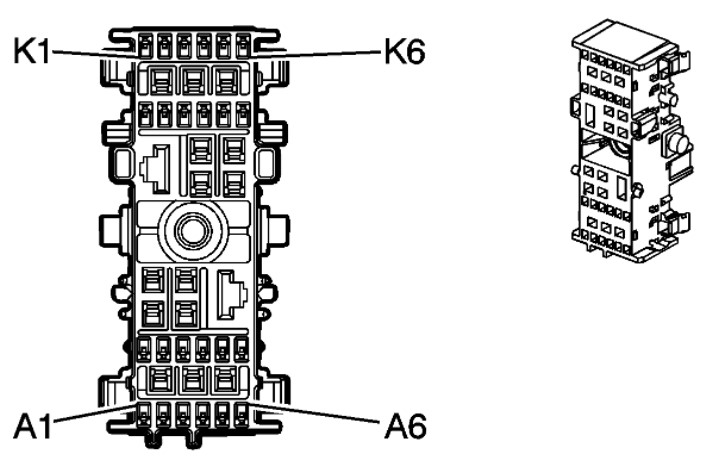
The next move is to recheck voltage at the same violet/white wire at the PCM. I'll find the connector in a bit.
Please Log in or Create an account to join the conversation.
- stspringer
-
Topic Author
- Offline
- New Member
-
- Posts: 17
- Thank you received: 2
Please Log in or Create an account to join the conversation.
- Matt T
-
- Offline
- Platinum Member
-

- Posts: 751
- Thank you received: 276
Please Log in or Create an account to join the conversation.
- stspringer
-
Topic Author
- Offline
- New Member
-
- Posts: 17
- Thank you received: 2
Sorry I thought you posted but it was Matt T
"The next move is to recheck voltage at the same violet/white wire at the PCM. I'll find the connector in a bit."
Please Log in or Create an account to join the conversation.
- stspringer
-
Topic Author
- Offline
- New Member
-
- Posts: 17
- Thank you received: 2
Do I have to pull the ignition switch, to check it? Can you give me some steps to check for voltage "at" instead of pulling the ignition switch? What is meant by circuit 2?
Thanks
Please Log in or Create an account to join the conversation.
- Matt T
-
- Offline
- Platinum Member
-
- Posts: 751
- Thank you received: 276
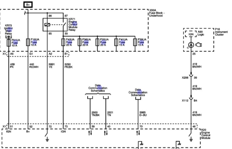
There is an Ign circuit from the fuse block to the PCM shown on the wiring diagram Tyler posted. That might be a good place to start since you already have access to the back of the fuse block.
Please Log in or Create an account to join the conversation.
- Tyler
-
- Offline
- Moderator
-
- Full time HACK since 2012
- Posts: 6126
- Thank you received: 1542
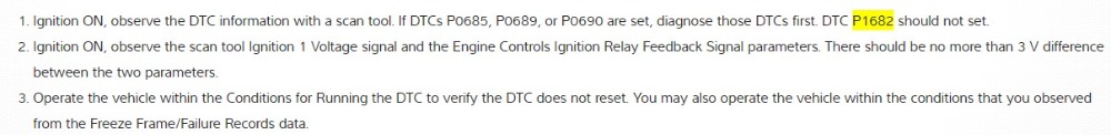
Matt T is right, the other two codes could be tied in. Do those codes reset if you clear them and attempt to start the car with everything connected?
P1682 has some pretty specific detection logic:
The circuits in question show up on several diagrams, but this was the only one that showed both:
As long as you're at the fuse box, it's easy enough to check fuse #40 and #51 for power on both sides of the fuse, key on. Use the test light, not the PP3.
What kind of scan tool do you have available? If it'll read OEM data, you can also check the associated PIDs in the ECM scan data to get a quick idea:
Please Log in or Create an account to join the conversation.
- Wightscope
-
- Offline
- Premium Member
-

- Posts: 132
- Thank you received: 30
Does P0615 starter relay control circuit come back when cleared as I would think that will set any time you remove the relay
With 12v on 86 there would have been 12v at the ECM driver output (and the bias voltage resistor/diode) but no current assuming transistor was open, if there was any (shorted) current voltage would drop to 0 across the relay coil.
Does the line from 86 go directly to ground? The dwg helpfully posted by Tyler has that section cut off.
I am thinking to look at what else is shared on that ground, neither a test light or relay coil has much of a draw so the high current might have fried the ground and anything beefier is going to be struggling - perhaps something linked to the codes, or the ECU...
Please Log in or Create an account to join the conversation.
- stspringer
-
Topic Author
- Offline
- New Member
-
- Posts: 17
- Thank you received: 2
I do not have a professinal scanner. I will do more tests based on the schematics you sent. I will not be testing today but I will try for testing tomorrow 06_30_21 or later today. I will get back to you.
Thanks
Please Log in or Create an account to join the conversation.
- stspringer
-
Topic Author
- Offline
- New Member
-
- Posts: 17
- Thank you received: 2
Did more testing and this is what I have so far. This is results from relay 62 ECM relay/ Power Train Relay.
Please Log in or Create an account to join the conversation.
- Wightscope
-
- Offline
- Premium Member
-
- Posts: 132
- Thank you received: 30
Please Log in or Create an account to join the conversation.