How does this ABS computer get power?
- Smeter12
-
 Topic Author
- Offline
- Senior Member
-

- Posts: 58
- Thank you received: 4
Background Info / the problem
- working on a 1990 Chrysler TC Maserati with a 3.0L V6 (never knew these things existed till it came into the shop....glorified K-car!!!). When applying the brake pedal, it feels like you are stepping on a stone.
Diagnostics completed so far
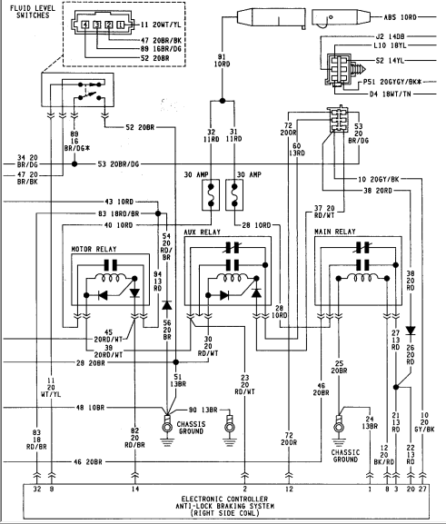
Attached is the "power" portion of the wiring schematics. The ABS controller has good grounds at pin 32 and pin 1. However, pin 3 has no power. From what I can tell, the "main" relay is powered side switched at pin 8 of the ABS controller. But with no power at pin 3, how the heck can pin 8 switch the "main" relay so that the coil of the "main" relay is energized. From what I can tell, when the ABS controller energizes pin 8 then pin 3 of the ABS controller should then provide power to rest of the ABS controller. But with that said, how can the ABS controller receive power when the ABS controller has no power to apply to pin 8. Obviously I am missing something on how the "main relay" works / how the ABS controller gets power - but what???
Looking for enlightenment on this one. Thanks in advance for your thoughts.
Please Log in or Create an account to join the conversation.
- Matt T
-
- Offline
- Platinum Member
-

- Posts: 751
- Thank you received: 276
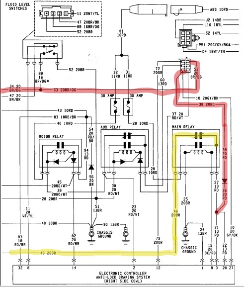
The red one can feed pin three plus a bunch of other ABS related stuff. That's the one I'd go after first. Aux relay looks like the easy place to check since it supplies voltage to both the coil and the power for that relay.
Please Log in or Create an account to join the conversation.
- Smeter12
-
Topic Author
- Offline
- Senior Member
-
- Posts: 58
- Thank you received: 4
The following pics are attached to this post:
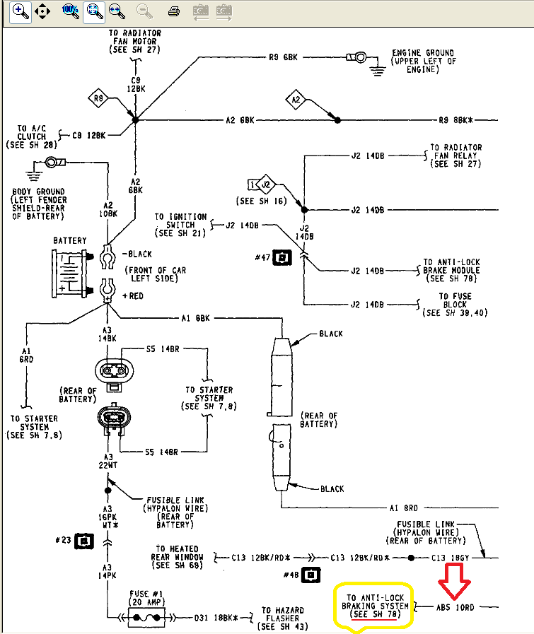
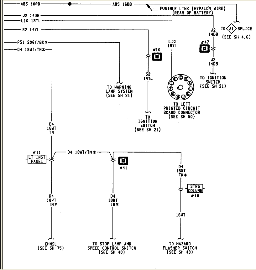
Sheet 23 - Battery / Power Distribution.
- On sheet 23 I have noted the ABS circuit at the bottom right of the page
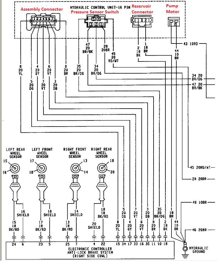
Sheet 77 - ABS Controller_Pg .
- In this pic I noted the wiring connectors on the ABS Hydraulic Control Unit - Assembly Connector; Pressure Switch/Sensor; reservoir connector; and pump motor connector
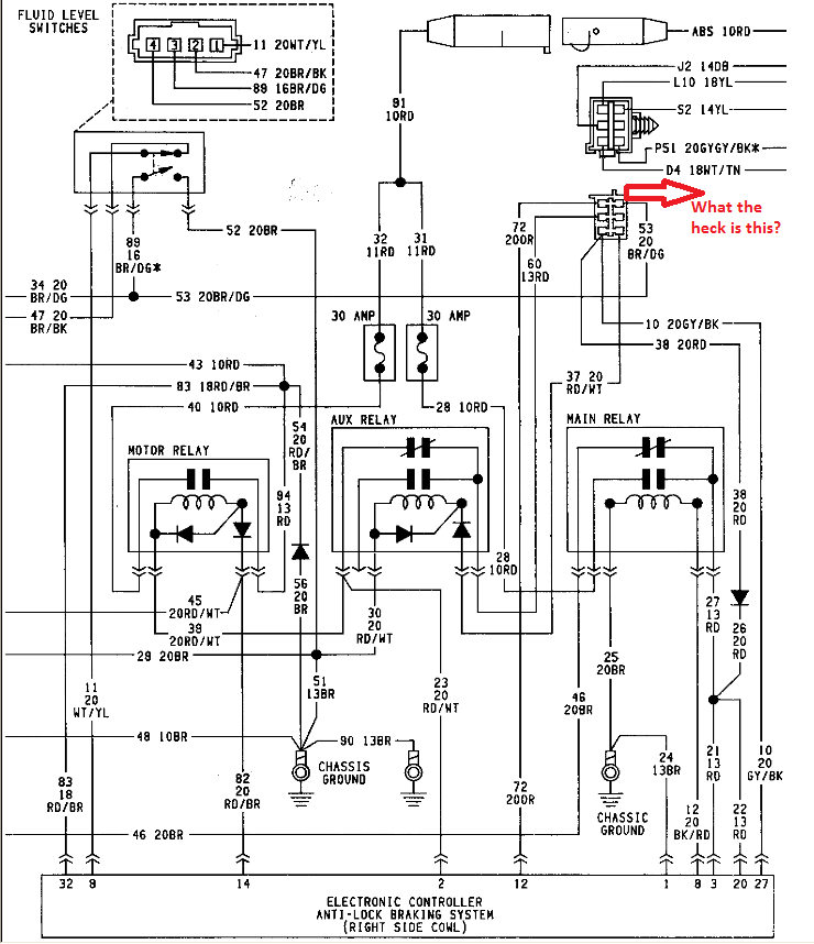
Sheet 78 - ABS Controller_Pg 2
- in this pic I have placed a red arrow asking "What the heck is this?". Is this a power distribution box?
Sheet 79 - ABS Controller_Pg 3
- attached this sheet as it completes the ABS Controller wiring schematics.
Again, I am not sure how the ABS computer gets powered up. Does the "AUX" relay send power to the distribution box and from there pins 12, 3, 20, and 27 get powered up on the ABS controller? But if that is the case, where does the "AUX" relay get its power from? Could there be something missing from the wiring schematics.
Hitting a wall on this one - can someone remove the wall for me?
Thanks in advance.
Please Log in or Create an account to join the conversation.
- Matt T
-
- Offline
- Platinum Member
-
- Posts: 751
- Thank you received: 276
Smeter12 wrote: Sheet 78 - ABS Controller_Pg 2
- in this pic I have placed a red arrow asking "What the heck is this?". Is this a power distribution box?
I thought it might've been a splice pack when I first saw it. Now I think it and the thing immediately above it might be the male and female halves of a 6 pin connector.
If that's what it is looks like power comes in from the ignition switch on J2 14DB then out on 60 13RD to the Aux relay. Thru' the NC contact then 23 20RD/WT to Pin 2 of the ABS module.
Smeter12 wrote: Again, I am not sure how the ABS computer gets powered up. Does the "AUX" relay send power to the distribution box and from there pins 12, 3, 20, and 27 get powered up on the ABS controller? But if that is the case, where does the "AUX" relay get its power from? Could there be something missing from the wiring schematics.
Looks like that "Aux" relay is used to disable ignition feed to ABS and control power to the motor relay. Appears to be energized by the "Warning Lamp System". Both it and the ignition feeds are referenced back to Sheet 21.
Please Log in or Create an account to join the conversation.
- Smeter12
-
Topic Author
- Offline
- Senior Member
-
- Posts: 58
- Thank you received: 4
I've attached 2 pics to this post
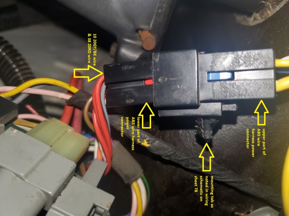
Pic 1 - ABS Computer_Power Connector
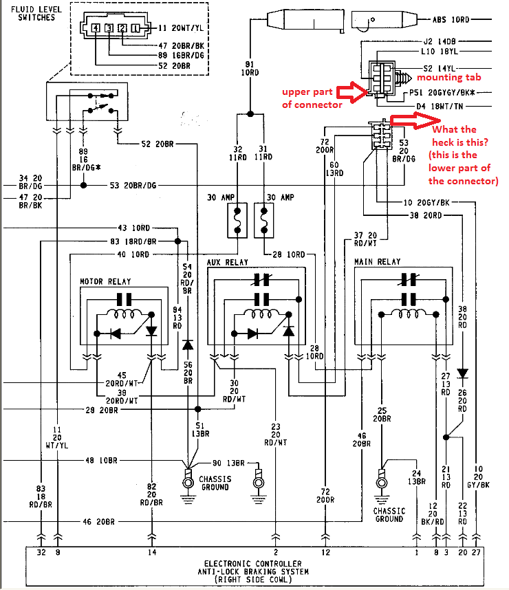
Pic 2 - Sheet 78_ABS Controller_Pg 2 (updated)
In an effort to provide some humor to this thread (hopefully not misunderstood humor), Lee Iacocca said to his electrical engineers "make a wiring schematic that is legible even when you take off your fire starting Coke bottle glasses!" The engineers accomplished this on sheet 78 (an updated pic has been attached to this post) when they depicted the wiring harness connector that provides power to the ABS electronic controller. On sheet 78, we can see the wiring harness (see Pic 2 attached this post) that provides power to the ABS control unit has been represented as opened - we can see both sides of the connector as the lower portion of the connector was facing up in your left hand and the upper portion facing up in your right hand. As per pic 1, we can see which cavity of the lower connector provides power to the ABS unit - note the position of the red (38 20RD) and grey/back (10 20GY/BK) wire - there be the power!!!
Mystery solved - that Matt T for giving me some clues.
Please Log in or Create an account to join the conversation.