Need help reading a wiring diagram
- Ash03
-
Topic Author
- Offline
- Premium Member
-

- Posts: 147
- Thank you received: 6
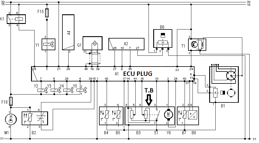
Original Diagram which I recently found

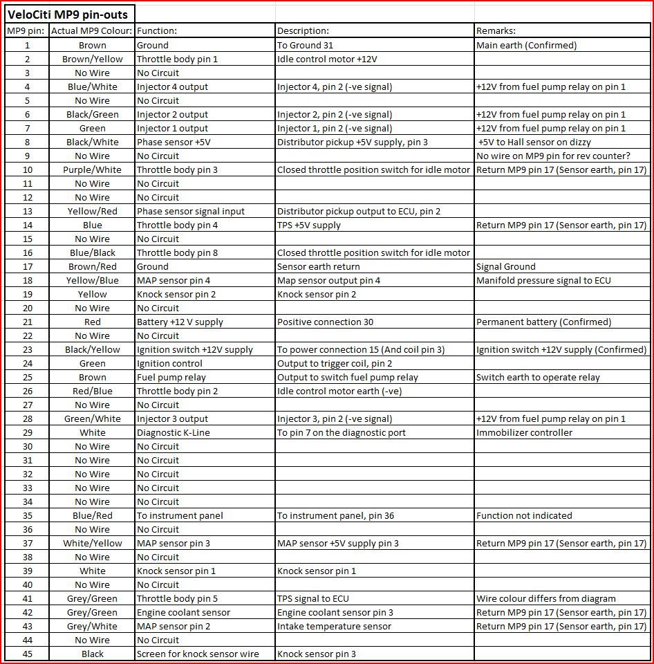
ECU pinout info that people use to convert standard to aftermarket management systems

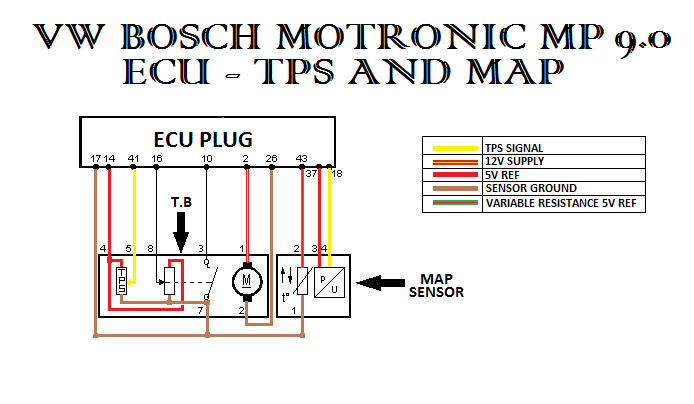
Here is an edit that I made to make it abit easier to view

Please Log in or Create an account to join the conversation.
- Tyler
-

- Offline
- Moderator
-

- Full time HACK since 2012
- Posts: 6064
- Thank you received: 1531
Kinda a weird setup! I see a 5V potentiometer for throttle blade position, two (?) idle validation switches, and two wires for the throttle motor itself.
The idle validation switches are strange... The one closest to the throttle motor (in the diagram) is pretty straightforward, but the one to the left LOOKS like a potentiometer. But, the pin out chart says it's a switch. :huh: Your voltage readings at the TB during operation may tell the rest of the story.
At the throttle body, I think you're looking for something like this:
Pin 4 = 5V
Pin 5 = 1-4V depending on the throttle blade
Pin 7 = 0V all the time (sensor ground)
Pin 1 = 12V, possibly pulse width modulated
Pin 2 = Ground, possibly pulse width modulated
Pin 3 is a switch input, and is going to have SOME kind of static voltage on it with the switch open, and 0V with the switch closed. Again, you'll have to do some checks and let us know what you find, since the diagram doesn't indicate the voltage level on that circuit. Same for Pin 8.
Please Log in or Create an account to join the conversation.
- Ash03
-
Topic Author
- Offline
- Premium Member
-

- Posts: 147
- Thank you received: 6
I previosuly did some checks and found the following
Pin1 - 0v
Pin2 - 0v
Pin3 - 11.6v
Pin4 - 5.03v
Pin5 - 5.52v
Pin7 - 0v
Pin8 - 5.52v
This is with the plug, unplugged and koeo
Im suspecting Pin3 because, how can there be voltage on 1 side of the switch and ground on the other side without some sort of load?
Please Log in or Create an account to join the conversation.
- Tyler
-

- Offline
- Moderator
-

- Full time HACK since 2012
- Posts: 6064
- Thank you received: 1531
Ash03 wrote: Hi Tyler
I previosuly did some checks and found the following
Pin1 - 0v
Pin2 - 0v
Pin3 - 11.6v
Pin4 - 5.03v
Pin5 - 5.52v
Pin7 - 0v
Pin8 - 5.52v
This is with the plug, unplugged and koeo
Im suspecting Pin3 because, how can there be voltage on 1 side of the switch and ground on the other side without some sort of load?
Those voltages sound OK to me, connector unplugged. Can you take the same readings again, plugged in + closed throttle, and plugged in + open throttle? That'll give us a better idea of how the inputs are working.
I believe Pin 3 is working correctly, due to this being a pull down design switch input. The ECU provides 12V to the switch inside the throttle body, which closes either with the throttle closed or throttle open (we don't know which yet). Switch closes, and that 12V is pulled to ground on the other side of the switch (Pin 7).
If you're interested, here's an older ScannerDanner video discussing switch inputs:
The cool part is that, because it's a pull down design, we now know that wire continuity is good for Pin 3.
Please Log in or Create an account to join the conversation.
- Ash03
-
Topic Author
- Offline
- Premium Member
-

- Posts: 147
- Thank you received: 6
Sent from my SM-G531H using Tapatalk
Please Log in or Create an account to join the conversation.
- Tyler
-

- Offline
- Moderator
-

- Full time HACK since 2012
- Posts: 6064
- Thank you received: 1531
Ash03 wrote: Hi sorry for the late reply, for some reason i did not get a notification about your post.. i did check the t.b properly it is working 100%.. the problem is with either the map sensor or the map sensor circuit
Sent from my SM-G531H using Tapatalk
Oooooh OK, my mistake! :silly:
IMO, the MAP sensor wiring should test like this:
Pin 1 = Signal ground, 0V all the time, plugged in/unplugged
Pin 2 = IAT signal, 1-4V plugged in, 5V unplugged
Pin 3 = MAP 5V supply, 5V all the time, plugged in/unplugged
Pin 4 = MAP signal
I'm gonna GUESS that the MAP will read over 3V (maybe closer to 4V) KOEO, with the manifold at atmospheric pressure, and closer to 1V with the engine running. I don't know exact specifications on this sensor/engine, those are just broad guidelines.
Please Log in or Create an account to join the conversation.
- Ash03
-
Topic Author
- Offline
- Premium Member
-

- Posts: 147
- Thank you received: 6
The original map sensor that was on this car was set at a default value, not changing with rpm. (Intake temp read -34degrees celsius and map read 134mbar)
I tested for 5v ref and ground everything seemed ok. I removed the sensor it smelt burnt (like burnt plastic)
Replaced the sensor
Now koeo im getting a proper barometric pressure(1034) and intake temp.
Start the car, it doesnt idle - but revs up only under wot. So i hook up my scantool and check readings while revving and it seems as if when the throttle is open im getting a vacuum reading(at idle it suppose to read around 500mbar. Wot it suppose to be close to the baro pressure at 1034, but at a 70degree t.b angle im only getting 520mbar. At one stage - at Wot it read 37mbar)
I hooked up a vacuum gauge to the intake manifold, at wot i get zero vacuum, at deceleration im getting 0.8bar vacuum then it settles at 0.6bar at idle - the engine is working as it should.
So i disconnected just the map sensor output wire from the map sensor plug. Car idles as if the map sensor unplugged (runs rich and idle fluctuates)
I check the map sensor output wire for voltage and i get around 1v at idle, voltage increases as the car revs up. (Seems normal to me)
I then check voltage on the same wire but on the ecu side - i get 2v at idle. With the dvom lead still attached to the wire, i join them up while the car is idling, dvom then reads 0.3-0.4v and the car dies.
Im heading towards a faulty ecu here.. just need more input before i make the call
Sent from my SM-G531H using Tapatalk
Please Log in or Create an account to join the conversation.
