Help us help you. By posting the year, make, model and engine near the beginning of your help request, followed by the symptoms (no start, high idle, misfire etc.) Along with any prevalent Diagnostic Trouble Codes, aka DTCs, other forum members will be able to help you get to a solution more quickly and easily!
circuit testing and confirming the bad
- Matronix
-
 Topic Author
- Offline
- Junior Member
-

Less
More
- Posts: 23
- Thank you received: 6
5 years 5 months ago #45071
by Matronix
circuit testing and confirming the bad was created by Matronix
undefined Question
Got an Audi in with an error on a 'reference voltage sensor circuit C', and a code for a DPF filter being unexpectetly high filled.
When starting cold the system worked and you see 13grams of filling of DPF (ash).. both calculated and expected are equal. As soon as the Sensor reference voltage problem shows up, you will see the filling rate bounce up rapidly, hence the error message for DPF on the instrument panel and code set.
When measuring 5v. circuit you will see the voltage being dropped to 3.x volt. (connected ofcourse, disconnected 5v.). Question now was, is this the sensor or is it the 5v. circuit (ECU). Since the code was set it's not wiring (measured inside ECU) or connectors.
I connected an incondessant (spelled correctly?) testlight and it took the circuit down about 4.3 volt. So the sensor is taking more current then the testlight. In this case, I condemned the sensor immediately, after learning a sensor is taking only miliamps. Also the labscope did not take the circuit down, it shows about 5v.
Is this a standard we can hang on to? Is a sensor always taking only miliamps?
Please Log in or Create an account to join the conversation.
- Matt T
-
- Offline
- Platinum Member
-

Less
More
- Posts: 751
- Thank you received: 276
5 years 5 months ago #45079
by Matt T
Replied by Matt T on topic circuit testing and confirming the bad
You made me check my 50mA light at 5V :silly:
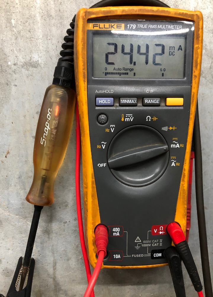
This is 5V LED light I made for testing 5V circuits.
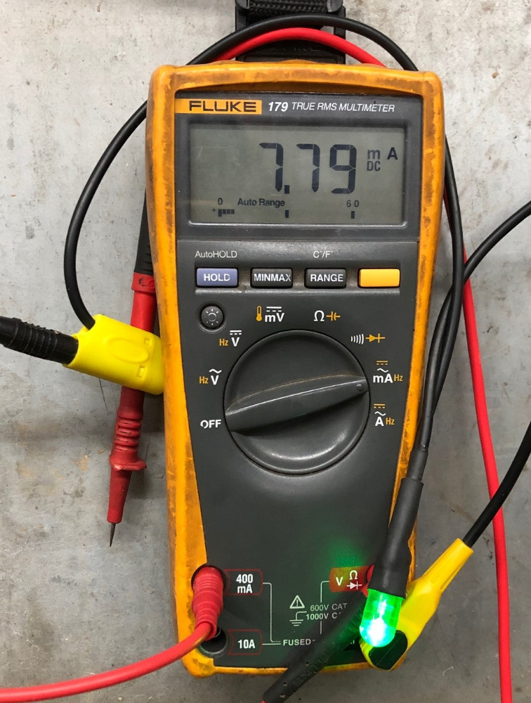
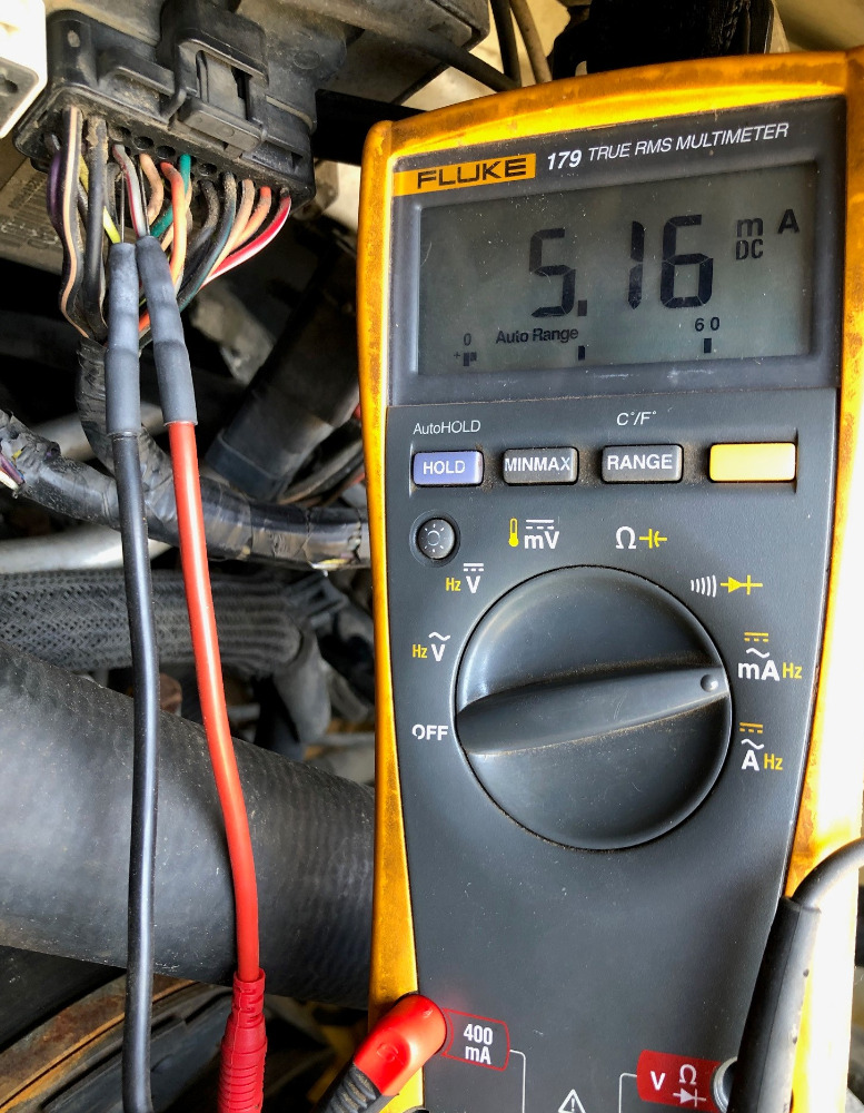
This one is grounding the CKP signal wire on a JTEC PCM. My 5V light lit up when I tried grounding the wire with it so I wanted to see how much current it'd supply.
This is 5V LED light I made for testing 5V circuits.
This one is grounding the CKP signal wire on a JTEC PCM. My 5V light lit up when I tried grounding the wire with it so I wanted to see how much current it'd supply.
Please Log in or Create an account to join the conversation.
- Matronix
-
Topic Author
- Offline
- Junior Member
-
Less
More
- Posts: 23
- Thank you received: 6
5 years 5 months ago #45080
by Matronix
Replied by Matronix on topic circuit testing and confirming the bad
The signal wire you can easily drop, since it's a real low current voltage. It's especially about the 5v. circuit, to confirm it's an ECU issue, dropping the 5v. or it's a sensor doing it. With more then one sensor on a line it's quite easy to check, disconnecting different sensors... this specific one I referred to had only 1 sensor on it, so it's a bit harder to condem one or the other.
In your tests it's clear it's taking several miliamps (the green led one is only 7.79ma). That should never take the 5v. down, unless indeed there is an issue. An other idea I had is taking 'a' sensor and put short leads with pins on it so you can plug it in any circuit to test. Ultimate question is still, with how many (mili)amps on average is a sensor putting the strain on a circuit") So how does it compare to a test light (led or bulb)
So how does it compare to a test light (led or bulb)
In your tests it's clear it's taking several miliamps (the green led one is only 7.79ma). That should never take the 5v. down, unless indeed there is an issue. An other idea I had is taking 'a' sensor and put short leads with pins on it so you can plug it in any circuit to test. Ultimate question is still, with how many (mili)amps on average is a sensor putting the strain on a circuit
So how does it compare to a test light (led or bulb) Please Log in or Create an account to join the conversation.
Time to create page: 0.263 seconds