Help us help you. By posting the year, make, model and engine near the beginning of your help request, followed by the symptoms (no start, high idle, misfire etc.) Along with any prevalent Diagnostic Trouble Codes, aka DTCs, other forum members will be able to help you get to a solution more quickly and easily!
Circuits sharing 5V reference voltage?
- Smeter12
-
 Topic Author
- Offline
- Senior Member
-

Less
More
- Posts: 58
- Thank you received: 4
5 years 5 months ago #44950
by Smeter12
Circuits sharing 5V reference voltage? was created by Smeter12
Okay... here we go.....
Background Info
- 1995 Jaguar XJS convertible with a 4.0L engine
- vehicle idles rough and lacks power when driving
Discovered problem
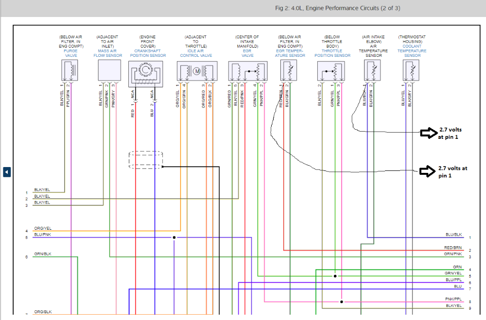
- air intake temp sensor (IAT) and EGR temp sensor (btw, as per my "guided component test component information" in my Verus scan tool, this EGR temp sensor generates a DC voltage signal that is sent to the ECM) both have 2.7 volts (i.e. the signal wire) with the wiring harnesses disconnected. You can see this information on the pic titled "1995_Jaguar XJS_Engine Performance_2 of 3_pg 1_v1" attached to this post.
What I think the problem is:
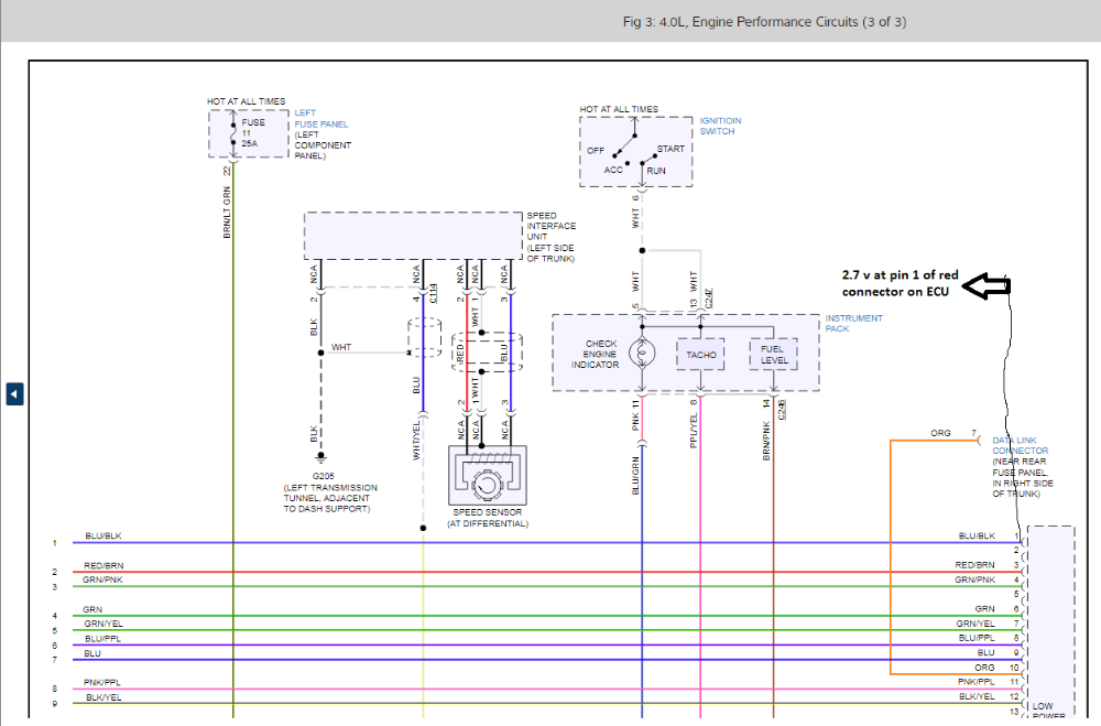
- because I also have 2.7 V right at pin 1 of the red connector on the ECU (see pic titled 1995_Jaguar XJS_Engine Performance_3 of 3_pg 1_v1), I believe somewhere in the wiring loom the EGR temp sensor (which should have NO voltage with the wiring harness disconnected and KOEO) signal circuit is grabbing voltage from the 5V reference to the IAT sensor signal circuit. Is this good logic? This problem maybe obvious to some, but before I start cutting wires I wanted to make sure I wasn't missing something.
As always - thoughts appreciated and thanks in advance.
Background Info
- 1995 Jaguar XJS convertible with a 4.0L engine
- vehicle idles rough and lacks power when driving
Discovered problem
- air intake temp sensor (IAT) and EGR temp sensor (btw, as per my "guided component test component information" in my Verus scan tool, this EGR temp sensor generates a DC voltage signal that is sent to the ECM) both have 2.7 volts (i.e. the signal wire) with the wiring harnesses disconnected. You can see this information on the pic titled "1995_Jaguar XJS_Engine Performance_2 of 3_pg 1_v1" attached to this post.
What I think the problem is:
- because I also have 2.7 V right at pin 1 of the red connector on the ECU (see pic titled 1995_Jaguar XJS_Engine Performance_3 of 3_pg 1_v1), I believe somewhere in the wiring loom the EGR temp sensor (which should have NO voltage with the wiring harness disconnected and KOEO) signal circuit is grabbing voltage from the 5V reference to the IAT sensor signal circuit. Is this good logic? This problem maybe obvious to some, but before I start cutting wires I wanted to make sure I wasn't missing something.
As always - thoughts appreciated and thanks in advance.
Please Log in or Create an account to join the conversation.
- Matt T
-
- Offline
- Platinum Member
-

Less
More
- Posts: 751
- Thank you received: 276
5 years 5 months ago #44951
by Matt T
That is highly unlikely. It's drawn as a conventional temp sensor circuit which will be supplied current limited voltage by the PCM. Never worked on a Jag but I'd expect 5V open circuit.
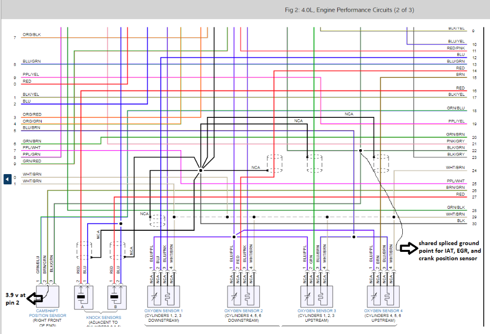
The reason EGR and IAT are both at 2.7V unplugged is probably because they're only being supplied 2.7V by the PCM. The 3.9V at the CMP is also suspect. All points to a problem with your 5V reference.
Replied by Matt T on topic Circuits sharing 5V reference voltage?
Smeter12 wrote: as per my "guided component test component information" in my Verus scan tool, this EGR temp sensor generates a DC voltage signal that is sent to the ECM
That is highly unlikely. It's drawn as a conventional temp sensor circuit which will be supplied current limited voltage by the PCM. Never worked on a Jag but I'd expect 5V open circuit.
The reason EGR and IAT are both at 2.7V unplugged is probably because they're only being supplied 2.7V by the PCM. The 3.9V at the CMP is also suspect. All points to a problem with your 5V reference.
The following user(s) said Thank You: Noah
Please Log in or Create an account to join the conversation.
- Noah
-

- Offline
- Moderator
-

Less
More
- Posts: 5028
- Thank you received: 1119
5 years 5 months ago #44952
by Noah
Replied by Noah on topic Circuits sharing 5V reference voltage?
It does say in the component test section of Shop Key that it generates a voltage, but this misinformation.
More correctly, it pulls 5v to ground as temperature increases. As evidenced by circuit test described, KOEO sensor disconnected, voltage should be 5v which is to be expected on just about any temperature sensing circuit.
I agree with Matt, your test results point to a problem with 5v supply from the PCM.
Please Log in or Create an account to join the conversation.
- Smeter12
-
Topic Author
- Offline
- Senior Member
-
Less
More
- Posts: 58
- Thank you received: 4
5 years 5 months ago #44973
by Smeter12
Replied by Smeter12 on topic Circuits sharing 5V reference voltage?
Troubleshooting this kind of circuit with this kind of problem (i.e. 2.7v at both the EGR temp sensor as well as IAT sensor) is new to me. I did replace the original computer with known good ECU and I still had 2.7v at the EGR temp sensor and the IAT sensor. This would tell me problem is with the car. So what could be a diagnostic approach on this problem? Use similar logic as one would when troubleshooting a downed vehicle bus system? Unplug all the 5V reference signal components that run off of the ECU's red connector (see attached pic) and then one by one connect the wiring harnesses of each 5V component while watching my voltage at the unplugged IAT sensor (i.e. some 5V reference component is bringing down the voltage on the 5V reference signal) go down to 2.7V?
Again, thoughts appreciated and thanks in advance.
Again, thoughts appreciated and thanks in advance.
Please Log in or Create an account to join the conversation.
- Smeter12
-
Topic Author
- Offline
- Senior Member
-
Less
More
- Posts: 58
- Thank you received: 4
5 years 5 months ago #44988
by Smeter12
Replied by Smeter12 on topic Circuits sharing 5V reference voltage?
In effort to update a resolution to this post, I would like to share the following "head up my bum bum" moment. To initially obtain a voltage reading for the 5V reference, I used a LED test light which has a voltage reading feature on it and I choose a poor ground as well as the clamp on this test light does not clamp well. This all lead to a 2.7 V reading. Later, I got out my high impedance volt meter, grounded my com to the battery and made a male connect to fit snuggly into the IAT sensor wiring harness. On my second go around, I got a 4.95V reading for my reference circuit. Hmmm - guess you can wrap this post up as "a clueless" moment from yours truly!! Learn from my mistake.
Please Log in or Create an account to join the conversation.
- Matt T
-
- Offline
- Platinum Member
-
Less
More
- Posts: 751
- Thank you received: 276
5 years 5 months ago #44997
by Matt T
Replied by Matt T on topic Circuits sharing 5V reference voltage?
Might not have been a bad ground on your test light. A low impedance tester like that can pull down a signal circuit. Useful for IDing Vref and signal on 3 wire sensors.
Please Log in or Create an account to join the conversation.
Time to create page: 0.311 seconds