Re:Re:Re:2015 Armada No Heat
- Tutti57
-
 Topic Author
- Offline
- Platinum Member
-

- Posts: 1098
- Thank you received: 253
I forgot that this is not just a solonoid that is opened or closed and thought I had no power at it from the AC auto amp, so I replaced that and when I didn't fix it I realized it's supposed to open and close from the AC auto amp based on temp knobs and only moves when the knobs are actually turned. It's got gears, not a solenoid. Both wires are grounded until the knob is turned then one side becomes a power depending on if it's opening or closing. Idiot, I knew this too. I took one apart like a year ago.
Knowing that, I have 10.5v on it when the temp knobs are turned. SI says it should be B+. I also have 10.5v coming out of the AC auto amp, so it's not high resistance between the two. Tested powers and grounds to the amp and all are good with near B+ in and 40mv on ground. My power probe makes the valve move with 12v.
Now, are the gears a little rough or something and my 12v blast is enough to move them but the "normal" 10.5v it's getting isn't, and maybe it would be enough for a new valve, or is my AC auto amp bad?
If you read my recent Pathfinder no heat post, you might understand why I'm questioning the new amp I put in it. My parts dept was also having a hard time determining the part number for some reason and had to contact Nissan about it, so I'm not exactly filled with confidence there.
I always struggle when numbers are like this because voltage drop is such a big concern. It seems ridiculous that it would be designed that way. It makes me want to just use a test light and focus less on the specific numbers, but I've definitely had cases where that would have burned me, so I don't know.
Sent from my moto g fast using Tapatalk
Please Log in or Create an account to join the conversation.
- Tyler
-

- Offline
- Moderator
-

- Full time HACK since 2012
- Posts: 6124
- Thank you received: 1541
You could also compare the amount of current the motor draws with your Power Probe to what it draws with the AC auto amp? Just an idea.
I think your instinct to use some kind of substitute load is right on. There's no resistance spec for this thing, of course, so you'll have to use your best judgement on how big a load. Maybe one or two amps?
My money is on a bad water valve.
")
Please Log in or Create an account to join the conversation.
- Tutti57
-
Topic Author
- Offline
- Platinum Member
-
- Posts: 1098
- Thank you received: 253
Sent from my moto g fast using Tapatalk
Please Log in or Create an account to join the conversation.
- Tutti57
-
Topic Author
- Offline
- Platinum Member
-
- Posts: 1098
- Thank you received: 253
With there being no fuse, what if it did internally short or the gears got jammed?
Since both wires are grounded normally, if I tried to provide power going from B+ to one side of the valve, my light would just light up, right? I don't think it would make the motor work.
Sent from my moto g fast using Tapatalk
Please Log in or Create an account to join the conversation.
- Tyler
-
- Offline
- Moderator
-
- Full time HACK since 2012
- Posts: 6124
- Thank you received: 1541
Tutti57 wrote: Right before I left yesterday I powered the valve with PP and let the truck idle while I cleaned up to see if I had heat flow through and I still didn't. I don't know how long that motor has to turn to open but I do think it's the valve.
Does this look like the valve in question?
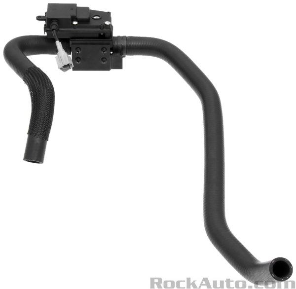
I was trying to get an idea of what kind of gear ratio it uses to turn the valve, but I can't really tell from pictures. :silly: Thought that might give us an idea of how long it takes to move the valve.
Speaking of, there's no position sensor in the valve, right? So I figure the AC auto amp has to be monitoring current on that driver circuit to make sure it doesn't strip the gears in the valve. Kinda like Chrysler/Dodge/Jeep HVAC actuators.
While I'm thinking out loud... Does the presence of the valve require special bleeding procedures? Or, can I just use my vacuum filler like normal?
Please Log in or Create an account to join the conversation.
- Tutti57
-
Topic Author
- Offline
- Platinum Member
-
- Posts: 1098
- Thank you received: 253
I will likely be replacing the valve and I'll dismantle it to see what is in there exactly.
Sent from my moto g fast using Tapatalk
Please Log in or Create an account to join the conversation.
- Tutti57
-
Topic Author
- Offline
- Platinum Member
-
- Posts: 1098
- Thank you received: 253
Sent from my moto g fast using Tapatalk
Please Log in or Create an account to join the conversation.
- Tyler
-
- Offline
- Moderator
-
- Full time HACK since 2012
- Posts: 6124
- Thank you received: 1541
Please Log in or Create an account to join the conversation.
- Tutti57
-
Topic Author
- Offline
- Platinum Member
-
- Posts: 1098
- Thank you received: 253
Here are the guts of the valve.
How would you have gone about this if you found one side of the hose cold, then 10v at the connector? I feel like I would have questioned that 10v and not known if it was ok or not if I did this all over again.

Sent from my moto g fast using Tapatalk
Please Log in or Create an account to join the conversation.
- Noah
-

- Offline
- Moderator
-
- Posts: 5028
- Thank you received: 1119
Good find, keep up the good work!
Please Log in or Create an account to join the conversation.
- Tyler
-
- Offline
- Moderator
-
- Full time HACK since 2012
- Posts: 6124
- Thank you received: 1541
Maybe I'm way off? But I still think a current waveform would be useful on these, depending on the nature of the failure. I'm imagining a known good is something like a window motor. Steady current with the valve turning, then high draw when it reaches the stops.
Mail me this valve and I'll play with it.
Please Log in or Create an account to join the conversation.
- Matt T
-

- Offline
- Platinum Member
-
- Posts: 751
- Thank you received: 276
Tyler wrote: Maybe I'm way off? But I still think a current waveform would be useful on these, depending on the nature of the failure. I'm imagining a known good is something like a window motor. Steady current with the valve turning, then high draw when it reaches the stops.
Sounds reasonable. You'll see the commutator segments if it's turning. And if the current doesn't go up the gears are likely stripped.
Please Log in or Create an account to join the conversation.
- Tyler
-
- Offline
- Moderator
-
- Full time HACK since 2012
- Posts: 6124
- Thank you received: 1541
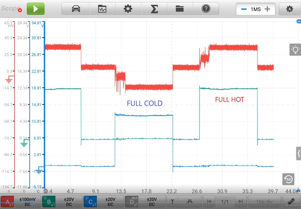
Red is motor current. 100mV/A. Blue and green are the two wires at the motor connector. This motor doesn't draw nearly as much current as I thought it would?
Here's zoomed in on the current waveform:
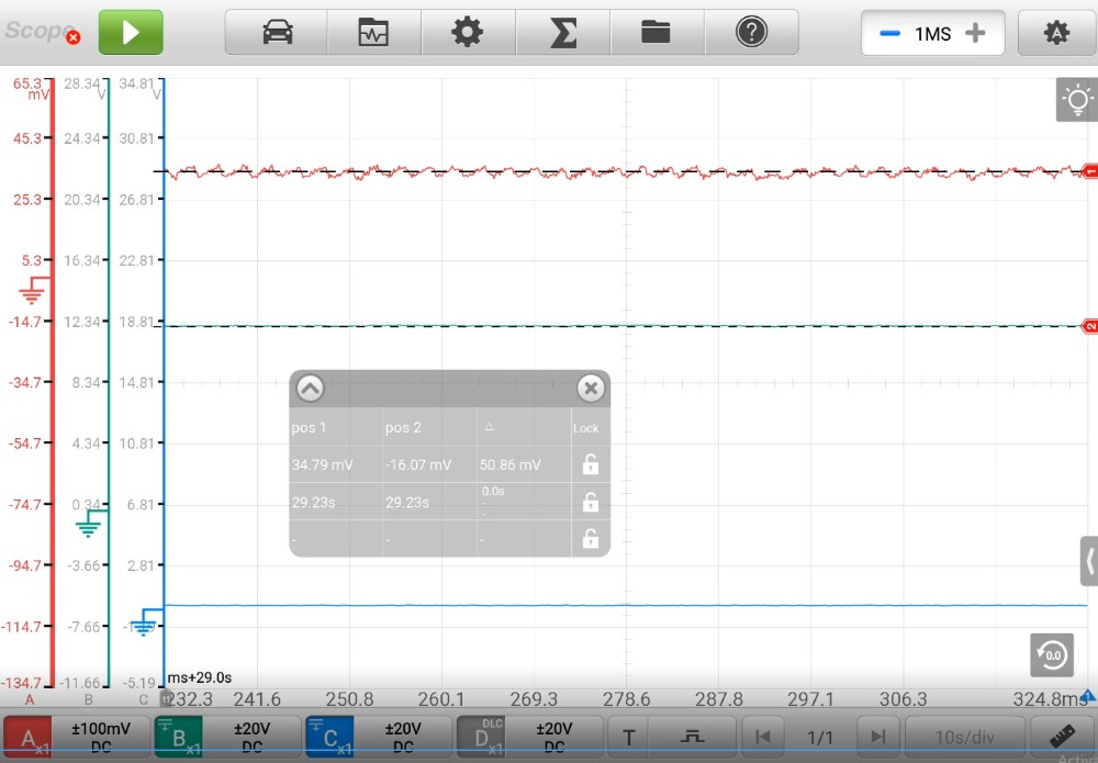
Steady state, the motor draws around 340mA. If you're substitute load testing this motor, something like a headlight would be way too much. :lol: A 194 bulb would be perfect.
Here's voltage on one of the control wires with the motor turning:
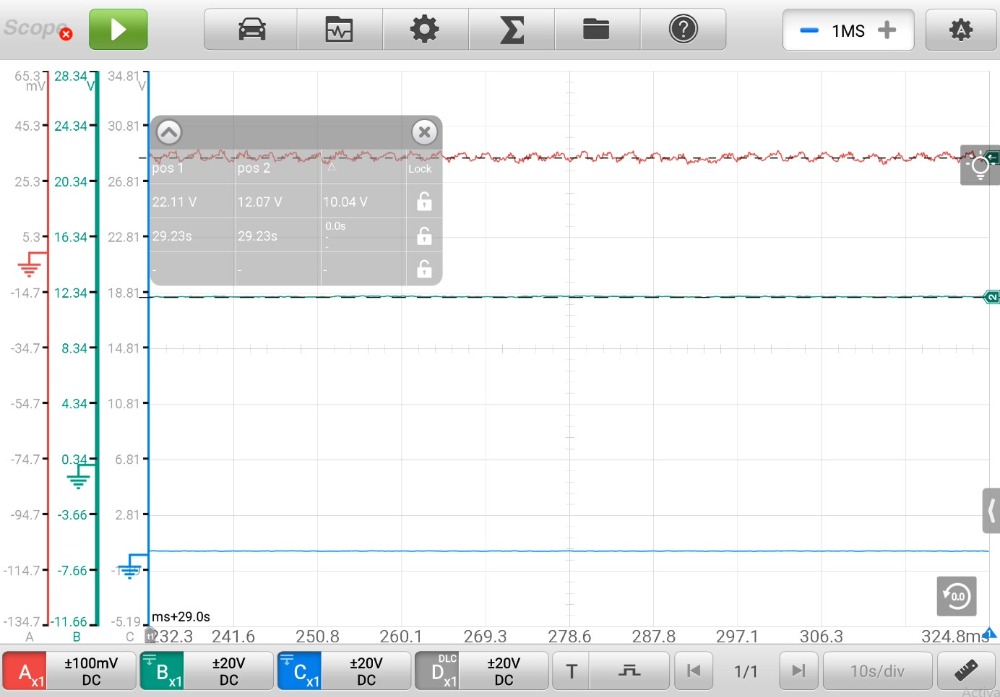
12-something volts. Took this with the engine running. Not sure if that makes a difference? :huh:
Please Log in or Create an account to join the conversation.
- Tutti57
-
Topic Author
- Offline
- Platinum Member
-
- Posts: 1098
- Thank you received: 253
Your 12v makes sense I guess, since the battery would probably be around 14v running. Mine at 10v koeo had 12v, so the same 2v difference?
Please Log in or Create an account to join the conversation.