Help us help you. By posting the year, make, model and engine near the beginning of your help request, followed by the symptoms (no start, high idle, misfire etc.) Along with any prevalent Diagnostic Trouble Codes, aka DTCs, other forum members will be able to help you get to a solution more quickly and easily!
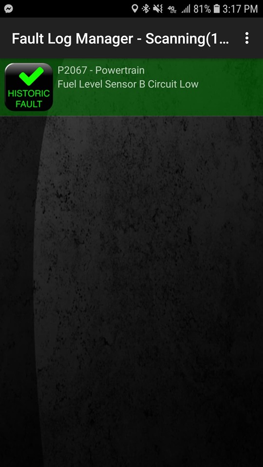
2013 Camaro ZL1 code P2067
- FASTFATBOY
-
 Topic Author
- Offline
- New Member
-

Less
More
- Posts: 1
- Thank you received: 0
5 years 8 months ago #42977
by FASTFATBOY
2013 Camaro ZL1 code P2067 was created by FASTFATBOY
Former tech here, kinda baffled. Been out of the game 12 years so Can bus is new to me.
Here is how it happened, driving down the road and the oil change reminder popped up in the DIC so at the next stop I shut it off and reset the reminder. As soon as I started the car it coded and the gas gauge went to empty.
I have replaced both senders and pump(dumb) I have also ohmed wires 44 and 45 to wire 9 in the PCM connector with the battery unhooked. Readings with 5 gallons of gas then added three gallons and started the car. The pump transferred fuel so everything back there is working properly. I also unhooked the ground to the under hood fuse box.
The gas gauge when I clear the code will move up slightly for a few seconds and when it re codes it will go dead again. Buddy has a scan tool and the fuel gauge failed a gauge sweep test.
Has these codes in the system:
ECM P2067
TCICM U1804
EBCM C0242
SCM U 0073-00 ans U0100
All is back together, car drives and starts fine just has no gas gauge and the "miles to empty" is inop.
Fuel Gauge Malfunction - DTC P0461-P0464 or P2066-P2068
Diagnostic Instructions
• Perform the Diagnostic System Check - Vehicleprior to using this diagnostic procedure.
• Review Strategy Based Diagnosisfor an overview of the diagnostic approach.
• Diagnostic Procedure Instructionsprovides an overview of each diagnostic category.
DTC DescriptorsDTC P0461
Fuel Level Sensor 1 Performance
DTC P0462
Fuel Level Sensor 1 Circuit Low Voltage
DTC P0463
Fuel Level Sensor 1 Circuit High Voltage
DTC P0464
Fuel Level Sensor 1 Circuit Intermittent
DTC P2066
Fuel Level Sensor 2 Performance
DTC P2067
Fuel Level Sensor 2 Circuit Low Voltage
DTC P2068
Fuel Level Sensor 2 Circuit High Voltage
Diagnostic Fault Information
Circuit
Short to Ground
High Resistance
Open
Short to Voltage
Signal Performance
Fuel Level Sensor 1 Signal
P0462
1
P0463
P0463
P0461
Fuel Level Sensor 2 Signal
P2067
1
P2068
P2068
P2066
Low Reference
—
1
P0463, P0464, P2068
P0463, P2068
P0461, P2066
1. Fuel Gauge Inoperative
Circuit/System Description
The primary fuel level sensor and, the secondary fuel level sensor change resistance based on fuel level. The engine control module (ECM) monitors the signal circuits of the primary fuel level sensor and the secondary fuel level sensor in order to determine the fuel level. When the fuel tank is full, the resistances of both fuel level sensors are low and the ECM senses a low signal voltage on both the signal circuits of the primary fuel level sensor and the secondary fuel level sensor. When the fuel tank is empty, the resistances of the fuel level sensors are high and the ECM senses a high signal voltage. The ECM uses the signal circuits of the primary fuel level sensor and the secondary fuel level sensor in order to calculate the percentage of remaining fuel in the tank. The ECM sends the fuel level percentage via the serial data circuit to the instrument cluster in order to control the fuel gauge.
Conditions for Running the DTC
• The engine is running.
• The system voltage is between 11–16 V.
Conditions for Setting the DTC
P0461 or P2066
The ECM detects a change in fuel level of less than a specified amount (typically 3–10 L or 0.8–2.6 gal) over a specified driving distance (typically 240–320 km or 150–200 miles).
P0462 or P2067
• The signal voltage is less than 0.25 V.
• The above conditions must be met for 5 seconds.
P0463 or P2068
• The signal voltage is greater than 4.7 V.
• The above conditions must be met for 5 seconds.
P0464
• The fuel level change is greater than 10%.
• The above conditions must be met for 30 seconds.
• DTC P0464 runs and fails 2 out of 3 test cycles.
Action Taken When the DTC Sets
• P0461, P0462, P0463, P0464, P2066, P2067 and P2068 are Type B DTCs.
• The fuel gauge defaults to empty.
• The low fuel indicator illuminates.
Conditions for Clearing the DTC
• P0461, P0462, P0463, P0464, P2066, P2067 and P2068 are Type B DTCs.
• The DTC becomes history when the conditions for setting the DTC are no longer present.
• The history DTC clears after 40 malfunction-free warm-up cycles.
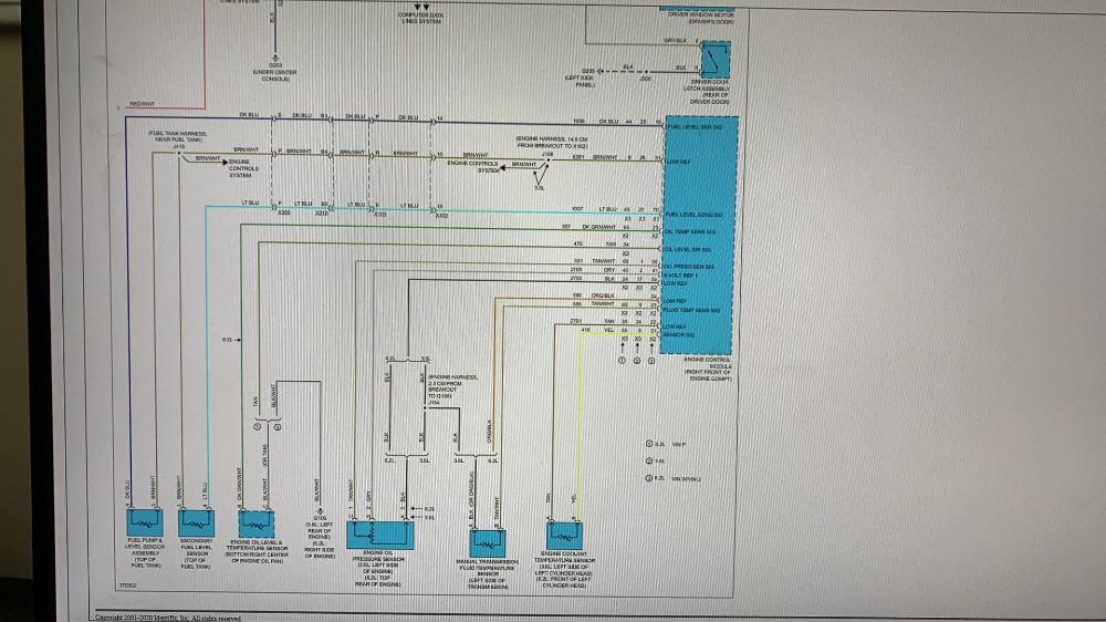
Reference InformationSchematic Reference
Instrument Cluster Schematics
Connector End View Reference
Component Connector End Views
Description and Operation
Instrument Cluster Description and Operation
Electrical Information Reference
• Circuit Testing
• Connector Repairs
• Testing for Intermittent Conditions and Poor Connections
• Wiring Repairs
DTC Type Reference
Powertrain Diagnostic Trouble Code (DTC) Type Definitions
Scan Tool Reference
Control Module Referencesfor scan tool information
Circuit/System Verification
1. Ignition ON.
2. Verify the scan tool Fuel Level Sensor parameters are between 0.5–3.5 V and vary with fuel level.
o If not between 0.5–3.5 V or does not vary with fuel level
Refer to Circuit/System Testing
o If between 0.5–3.5 V and varies with fuel level
3. Verify that all fuel level gauge sweeps when performing the scan tool Instrument Cluster Gauge Sweep test.
o If the fuel level gauge does not sweep
Replace the P16 instrument cluster
o If the fuel level gauge sweeps
4. All OK.
Circuit/System Testing
1. Ignition OFF and all vehicle systems OFF, disconnect the harness connector at the appropriate fuel level sensor. It may take up to 2 minutes for all vehicle systems to power down.
2. Test for less than 10 Ω between the low reference circuit terminal 3 and ground.
o If 10 Ω or greater
3.
1. Ignition OFF, disconnect the harness connector at the K20 Engine Control Module.
2. Test for less than 2 Ω in the low reference circuit end to end.
If 2 Ω or greater, repair the open/high resistance in the circuit.
If less than 2 Ω, replace the K20 Engine Control Module.
4.
o If less than 10 Ω
5. Ignition ON.
6. Verify the scan tool Remaining Fuel In Tank parameter is less than 5%.
o If 5% or greater
7.
0. Ignition OFF, disconnect the harness connector at the K20 Engine Control Module.
1. Test for infinite resistance between the signal circuit terminal 4 and ground.
If less than infinite resistance, repair the short to ground on the circuit.
If infinite resistance, replace the K20 Engine Control Module.
8.
o If less than 5%
9. Install a 3 A fused jumper wire between the signal circuit terminal 4 and the low reference circuit terminal 3.
10. Verify the scan tool Remaining Fuel In Tank is greater than 90%.
o If 90% or less
11.
0. Ignition OFF, disconnect the harness connector at the K20 Engine Control Module, ignition ON.
1. Test for less than 1 V between the signal circuit and ground.
If 1 V or greater, repair the short to voltage on the circuit.
If less than 1 V
2. Ignition OFF
3. Test for less than 2 Ω in the signal circuit end to end.
If 2 Ω or greater, repair the open/high resistance in the circuit.
If less than 2 Ω, replace the K20 Engine Control Module.
12.
o If greater than 90%
13. Test or replace the appropriate fuel level sensor.
Component Testing
1. Ignition OFF, remove the appropriate fuel level sender.
2. Sweep the fuel level sensor through its full range of motion while measuring resistance between the signal terminal 4 and the low reference terminal 3.
3. Test for a minimum resistance value of 37–43 Ω and a maximum value of 245–255 Ω without any spikes or dropouts.
o If minimum resistance is not 37–43 Ω, maximum resistance is not 245–255 Ω, or if there are any spikes or dropouts
Replace the fuel level sensor.
o If minimum resistance is 37–43 Ω, maximum resistance is 245–255 Ω, and if there are no spikes or dropouts
4. All OK.
Any help appreciated
Here is how it happened, driving down the road and the oil change reminder popped up in the DIC so at the next stop I shut it off and reset the reminder. As soon as I started the car it coded and the gas gauge went to empty.
I have replaced both senders and pump(dumb) I have also ohmed wires 44 and 45 to wire 9 in the PCM connector with the battery unhooked. Readings with 5 gallons of gas then added three gallons and started the car. The pump transferred fuel so everything back there is working properly. I also unhooked the ground to the under hood fuse box.
The gas gauge when I clear the code will move up slightly for a few seconds and when it re codes it will go dead again. Buddy has a scan tool and the fuel gauge failed a gauge sweep test.
Has these codes in the system:
ECM P2067
TCICM U1804
EBCM C0242
SCM U 0073-00 ans U0100
All is back together, car drives and starts fine just has no gas gauge and the "miles to empty" is inop.
Fuel Gauge Malfunction - DTC P0461-P0464 or P2066-P2068
Diagnostic Instructions
• Perform the Diagnostic System Check - Vehicleprior to using this diagnostic procedure.
• Review Strategy Based Diagnosisfor an overview of the diagnostic approach.
• Diagnostic Procedure Instructionsprovides an overview of each diagnostic category.
DTC DescriptorsDTC P0461
Fuel Level Sensor 1 Performance
DTC P0462
Fuel Level Sensor 1 Circuit Low Voltage
DTC P0463
Fuel Level Sensor 1 Circuit High Voltage
DTC P0464
Fuel Level Sensor 1 Circuit Intermittent
DTC P2066
Fuel Level Sensor 2 Performance
DTC P2067
Fuel Level Sensor 2 Circuit Low Voltage
DTC P2068
Fuel Level Sensor 2 Circuit High Voltage
Diagnostic Fault Information
Circuit
Short to Ground
High Resistance
Open
Short to Voltage
Signal Performance
Fuel Level Sensor 1 Signal
P0462
1
P0463
P0463
P0461
Fuel Level Sensor 2 Signal
P2067
1
P2068
P2068
P2066
Low Reference
—
1
P0463, P0464, P2068
P0463, P2068
P0461, P2066
1. Fuel Gauge Inoperative
Circuit/System Description
The primary fuel level sensor and, the secondary fuel level sensor change resistance based on fuel level. The engine control module (ECM) monitors the signal circuits of the primary fuel level sensor and the secondary fuel level sensor in order to determine the fuel level. When the fuel tank is full, the resistances of both fuel level sensors are low and the ECM senses a low signal voltage on both the signal circuits of the primary fuel level sensor and the secondary fuel level sensor. When the fuel tank is empty, the resistances of the fuel level sensors are high and the ECM senses a high signal voltage. The ECM uses the signal circuits of the primary fuel level sensor and the secondary fuel level sensor in order to calculate the percentage of remaining fuel in the tank. The ECM sends the fuel level percentage via the serial data circuit to the instrument cluster in order to control the fuel gauge.
Conditions for Running the DTC
• The engine is running.
• The system voltage is between 11–16 V.
Conditions for Setting the DTC
P0461 or P2066
The ECM detects a change in fuel level of less than a specified amount (typically 3–10 L or 0.8–2.6 gal) over a specified driving distance (typically 240–320 km or 150–200 miles).
P0462 or P2067
• The signal voltage is less than 0.25 V.
• The above conditions must be met for 5 seconds.
P0463 or P2068
• The signal voltage is greater than 4.7 V.
• The above conditions must be met for 5 seconds.
P0464
• The fuel level change is greater than 10%.
• The above conditions must be met for 30 seconds.
• DTC P0464 runs and fails 2 out of 3 test cycles.
Action Taken When the DTC Sets
• P0461, P0462, P0463, P0464, P2066, P2067 and P2068 are Type B DTCs.
• The fuel gauge defaults to empty.
• The low fuel indicator illuminates.
Conditions for Clearing the DTC
• P0461, P0462, P0463, P0464, P2066, P2067 and P2068 are Type B DTCs.
• The DTC becomes history when the conditions for setting the DTC are no longer present.
• The history DTC clears after 40 malfunction-free warm-up cycles.
Reference InformationSchematic Reference
Instrument Cluster Schematics
Connector End View Reference
Component Connector End Views
Description and Operation
Instrument Cluster Description and Operation
Electrical Information Reference
• Circuit Testing
• Connector Repairs
• Testing for Intermittent Conditions and Poor Connections
• Wiring Repairs
DTC Type Reference
Powertrain Diagnostic Trouble Code (DTC) Type Definitions
Scan Tool Reference
Control Module Referencesfor scan tool information
Circuit/System Verification
1. Ignition ON.
2. Verify the scan tool Fuel Level Sensor parameters are between 0.5–3.5 V and vary with fuel level.
o If not between 0.5–3.5 V or does not vary with fuel level
Refer to Circuit/System Testing
o If between 0.5–3.5 V and varies with fuel level
3. Verify that all fuel level gauge sweeps when performing the scan tool Instrument Cluster Gauge Sweep test.
o If the fuel level gauge does not sweep
Replace the P16 instrument cluster
o If the fuel level gauge sweeps
4. All OK.
Circuit/System Testing
1. Ignition OFF and all vehicle systems OFF, disconnect the harness connector at the appropriate fuel level sensor. It may take up to 2 minutes for all vehicle systems to power down.
2. Test for less than 10 Ω between the low reference circuit terminal 3 and ground.
o If 10 Ω or greater
3.
1. Ignition OFF, disconnect the harness connector at the K20 Engine Control Module.
2. Test for less than 2 Ω in the low reference circuit end to end.
If 2 Ω or greater, repair the open/high resistance in the circuit.
If less than 2 Ω, replace the K20 Engine Control Module.
4.
o If less than 10 Ω
5. Ignition ON.
6. Verify the scan tool Remaining Fuel In Tank parameter is less than 5%.
o If 5% or greater
7.
0. Ignition OFF, disconnect the harness connector at the K20 Engine Control Module.
1. Test for infinite resistance between the signal circuit terminal 4 and ground.
If less than infinite resistance, repair the short to ground on the circuit.
If infinite resistance, replace the K20 Engine Control Module.
8.
o If less than 5%
9. Install a 3 A fused jumper wire between the signal circuit terminal 4 and the low reference circuit terminal 3.
10. Verify the scan tool Remaining Fuel In Tank is greater than 90%.
o If 90% or less
11.
0. Ignition OFF, disconnect the harness connector at the K20 Engine Control Module, ignition ON.
1. Test for less than 1 V between the signal circuit and ground.
If 1 V or greater, repair the short to voltage on the circuit.
If less than 1 V
2. Ignition OFF
3. Test for less than 2 Ω in the signal circuit end to end.
If 2 Ω or greater, repair the open/high resistance in the circuit.
If less than 2 Ω, replace the K20 Engine Control Module.
12.
o If greater than 90%
13. Test or replace the appropriate fuel level sensor.
Component Testing
1. Ignition OFF, remove the appropriate fuel level sender.
2. Sweep the fuel level sensor through its full range of motion while measuring resistance between the signal terminal 4 and the low reference terminal 3.
3. Test for a minimum resistance value of 37–43 Ω and a maximum value of 245–255 Ω without any spikes or dropouts.
o If minimum resistance is not 37–43 Ω, maximum resistance is not 245–255 Ω, or if there are any spikes or dropouts
Replace the fuel level sensor.
o If minimum resistance is 37–43 Ω, maximum resistance is 245–255 Ω, and if there are no spikes or dropouts
4. All OK.
Any help appreciated
Please Log in or Create an account to join the conversation.
Time to create page: 0.208 seconds