Dodge MK1 - PCI Bus signal question
- Orchid70
-
 Topic Author
- Offline
- Junior Member
-

- Posts: 21
- Thank you received: 1
Have to edit here - I have two cars with communicaton problems and I mixed them together.
Sweden (so, its hard to find nolage and spare parts here)
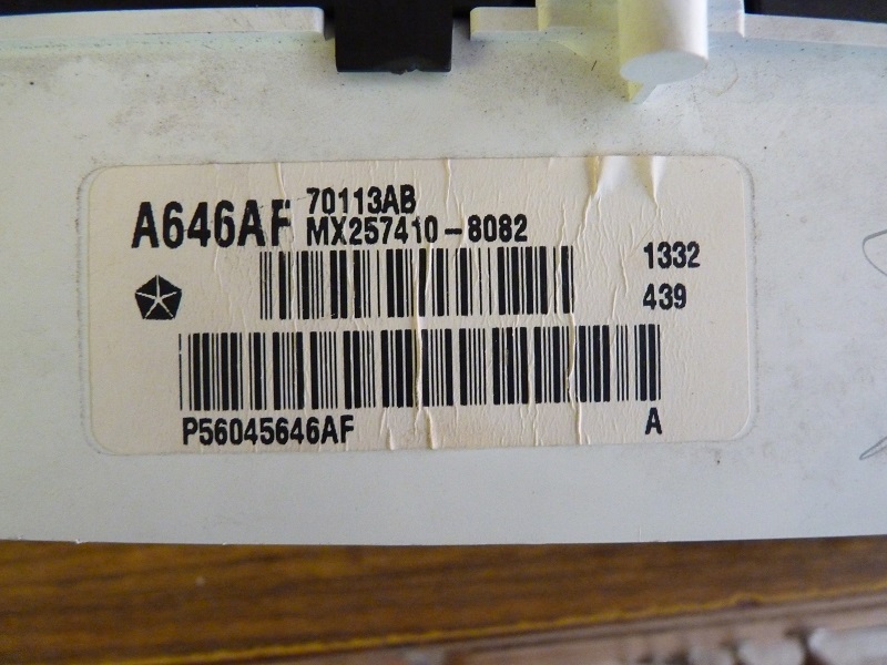
Dodge Durango 2002
4,7 V8
Motorola PCM
VIN: 1B4HR38N32F212883
Problem:
After some times storage the dash went DEAD (Dont know if No Bus - message has been present before, its the wife of our friend, that has driven the car in the past)
No connection with anything else but engine ECU, with SnapOn Verus
Fault code originally: P1698 - No bus communication
Car starts and drives
So there is 12V at dash and at OBD2 port and at PCM
There is ground
There arnt any shorts to ground
I can follow the PCI Bus wire from dash to PCM with Tone Generator
But this is what I wonder:
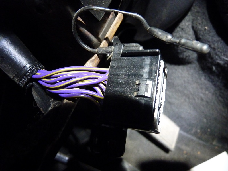
Measuring voltage at dash - at OBD port - at PCM at the PCI Bus wire (violet/yellow inside cabin and white/violet at PCM, pin 38 - black Connector C1) I get totally different voltage inside the cabin and at PCM.
At PCM ~ 0-7,5V (as they should reading the Service book)
At OBD port ~ -150-300mV
At Dash ~ -50-110mV
Should not all tha wave forms be equal, no matter where I measure?
The front panels inside the cabin are removed (A/C and lighting buttons)
I filmed these:
At Dash:
At OBD:
AT PCM:
Planing on trying to pull a wire between the PCI Bus pins between PCM and OBD and try to read car. Id like to know IF the PCM needs chaning - because I have no way of just testing an other one. Most likley I have to order one from USA, if thats the problem.
Thanks.
Please Log in or Create an account to join the conversation.
- Orchid70
-
Topic Author
- Offline
- Junior Member
-
- Posts: 21
- Thank you received: 1
Hooked up SnapOn:
Got into engine ECU: No fault codes and could monitor values.
No connection to any other system.
On top of this I have found a water leak. I thought I had been careless and not closed the door properly.... but it was not that.
The drivers (left) foot well was soaked with water. I vakuumed it out, lifted the foam rubber plate under the mat, put newspapers on the bottom - and left the mat open with a heating fan on, so the foam is dry. Today we had a short rain storm again - and the dry newspapers were wet all of the sudden again. It seems to be getting particularly wet, under neath the plastic cover that runs on the doorstep, with all the wiring to the rear of the car.
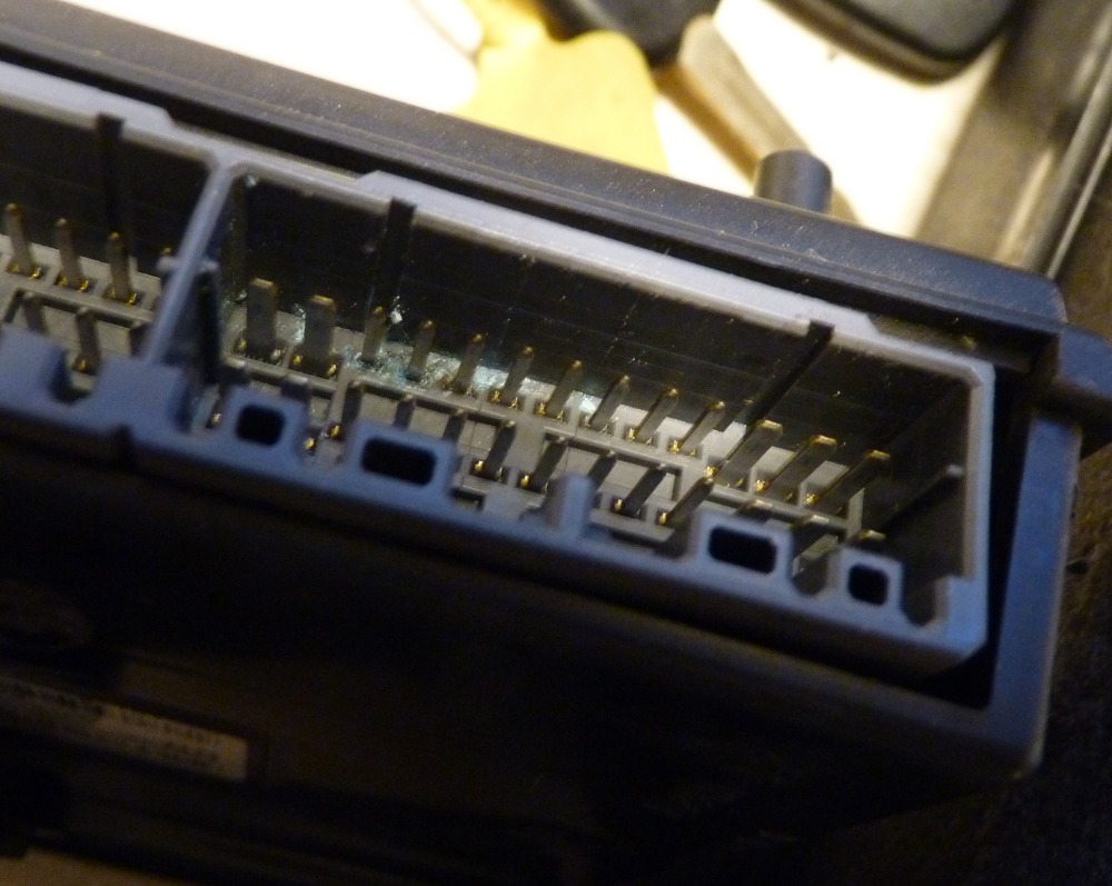
I have had the CTM out, placed under the drivers side kick panel. I could see small amount of blue corrotion on the connector pins - nothing major and everything inside it looked fine.
Please Log in or Create an account to join the conversation.
- Hardtopdr2
-
- Offline
- Platinum Member
-

- Posts: 853
- Thank you received: 150
Please Log in or Create an account to join the conversation.
- Orchid70
-
Topic Author
- Offline
- Junior Member
-
- Posts: 21
- Thank you received: 1
Thank you!
I do have the wiring (its NGC wiring I figured out) diagrams as wel as the Service book on pdf. And Mitchel.
Please Log in or Create an account to join the conversation.
- Orchid70
-
Topic Author
- Offline
- Junior Member
-
- Posts: 21
- Thank you received: 1
0,2 ohm between PCM and OBD.
Please Log in or Create an account to join the conversation.
- Hardtopdr2
-
- Offline
- Platinum Member
-
- Posts: 853
- Thank you received: 150
Look at the wire for pcm is there green crusties on either terminal and does it creep into the wire sheath? If so cut the bad section out or replace the whole wire with terminal ends.
Start by unplugging each module while monitering the bus network. Once the signal clears up to a square wave check that modules wiring you disconnected and ohm check wiring. If wiring is ok the module you disconnected is bad.
Also check power and grounds for all modules on that bus network. The same way you just did for the dlc wires.
Please Log in or Create an account to join the conversation.
- Orchid70
-
Topic Author
- Offline
- Junior Member
-
- Posts: 21
- Thank you received: 1
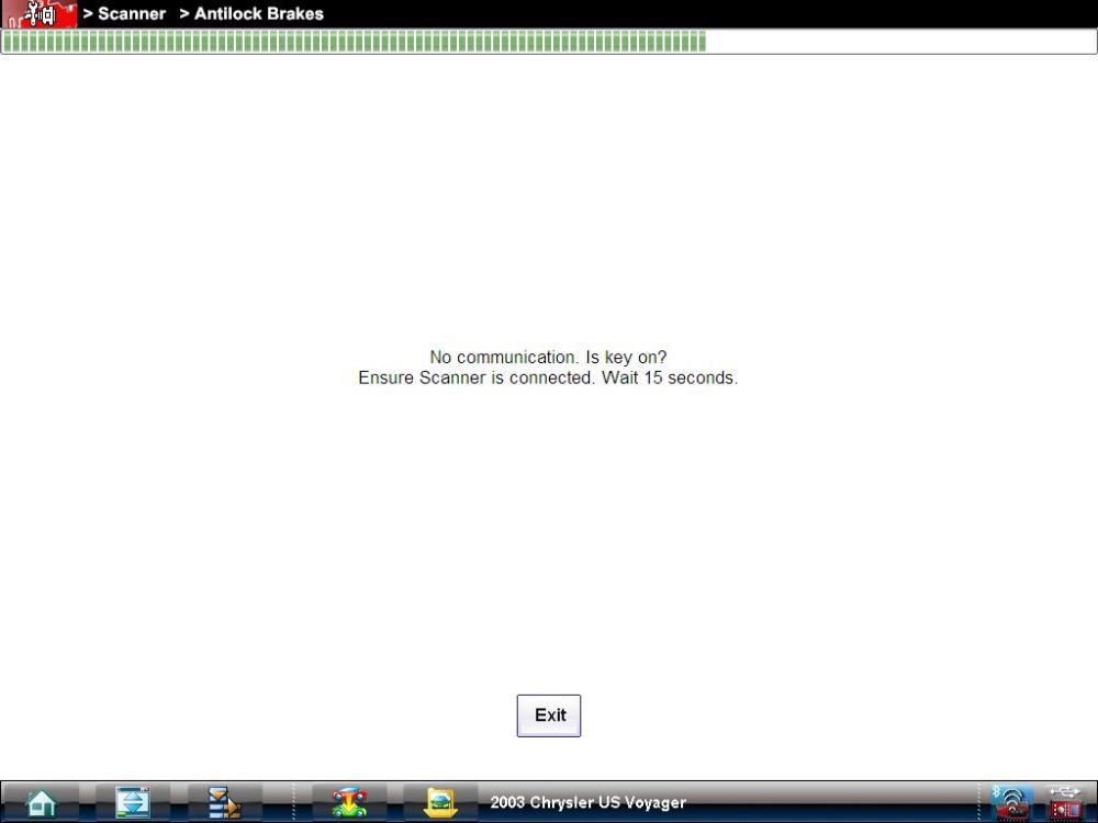
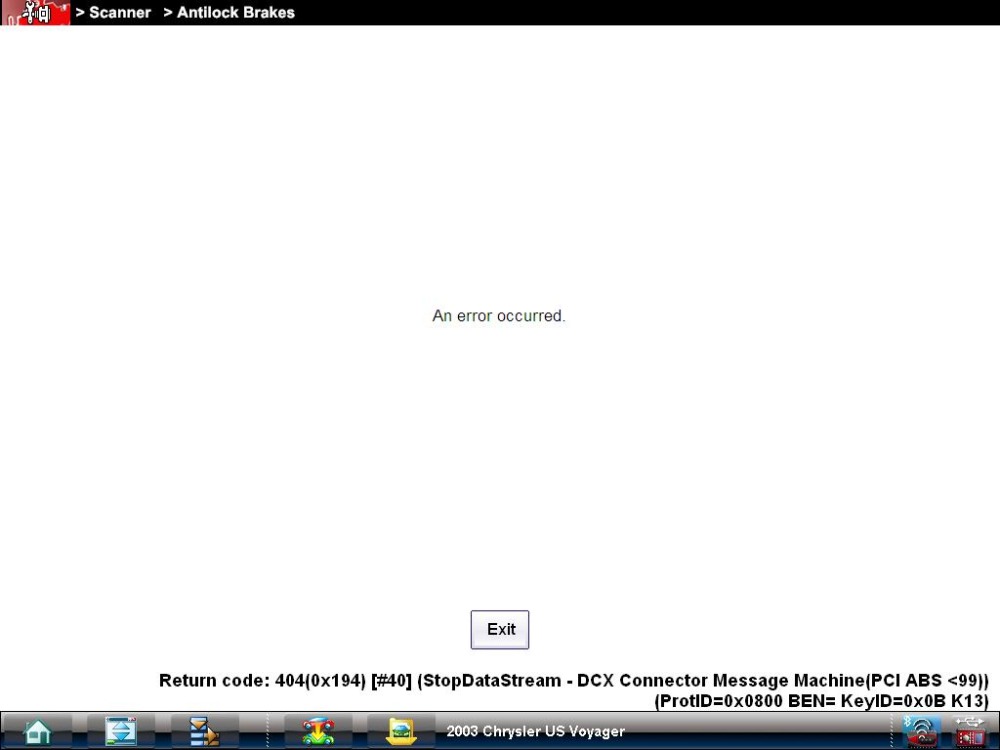
I have taken the SnapOn Verus to my friends Chrysler to try to read it - and it was the same:
Engine read ok
While trying to read any other ECU - the dash lights started going on and off - like it was doing a self test - and no connection with OBD reader.
After that SRS light came on!!
So - my code reader cannot do these cars

Therefor we cannot rely on those results!
And thats why I took the dash back into the kitchen
")
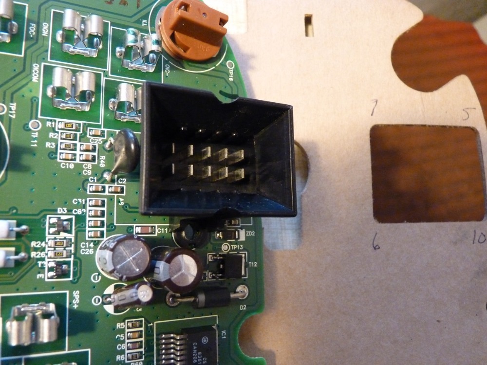
This time I put 12V on pin number 6 and 7 on connector 1 (right hand side)
And ground on pins 4 and 5.
Dead.
Then I put multimeter on pin 1 to see if I hade anyting coming out. The multimeter went straight down to zero.
The Dash is so simple and when I didnt see anything wrong with it in the beginning, I thought it was ok.
We'll try to measure us to the broken regulator.
When I googled this in the beginning, there wasnt much about broken instrument clusters to find and when Snap On couldnt connect to enything else but engine ECU..... on the wild goose chase I went....
So, I thought - could the signal get low the closer I get the instrument cluster, because of the dash was missing?
Please Log in or Create an account to join the conversation.
- Hardtopdr2
-
- Offline
- Platinum Member
-
- Posts: 853
- Thank you received: 150
Also pins 6 and 14 are data lines 0- 5 volts. 12 volts being feed into it can potentially cook a module. Pin 16 should be the only 12 volt wire.
Please Log in or Create an account to join the conversation.
- Orchid70
-
Topic Author
- Offline
- Junior Member
-
- Posts: 21
- Thank you received: 1
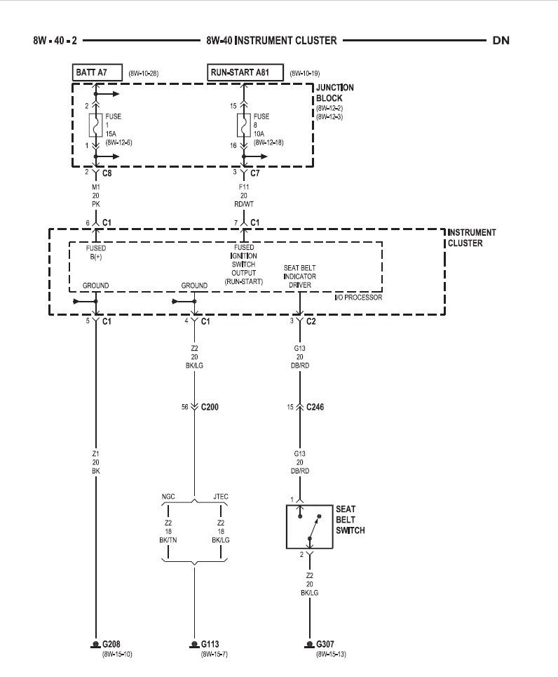
Below diagram for the whole dash for Dodge 2002 as pdf. There is no pin14.
Please Log in or Create an account to join the conversation.
- Hardtopdr2
-
- Offline
- Platinum Member
-
- Posts: 853
- Thank you received: 150
Please Log in or Create an account to join the conversation.
- Hardtopdr2
-
- Offline
- Platinum Member
-
- Posts: 853
- Thank you received: 150
Please Log in or Create an account to join the conversation.
- Orchid70
-
Topic Author
- Offline
- Junior Member
-
- Posts: 21
- Thank you received: 1
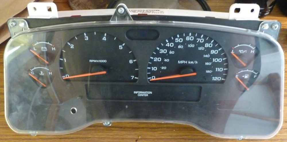
When I wrote dash - I ment Instrument Cluster. Thats what I was trying to see if it showed any life, what so ever, at the kitchen table. And it didnt.
There should have been 5V output at the pin 1 in connection 1, on the instrument cluster.
Location of the pins are written on the board, in the pic below (for future reference).
PS - the whole instrument cluster wiring is in the pdf file, in my previous comment. But only to the cluster.
Ill be off soon to see if we can find the broken power regulator or what evere has happened on the intrument cluster. I do hace a friend (the one with the Chrysler) who has possibility to bechs tests some electric boards - not PCM's unfortunatelly.
I will post the wiring diagrams a bit later today, just incase.
Thank you, dearest!!!
Please Log in or Create an account to join the conversation.
- Orchid70
-
Topic Author
- Offline
- Junior Member
-
- Posts: 21
- Thank you received: 1
Located to the right of the OBD port.
Please Log in or Create an account to join the conversation.
- Hardtopdr2
-
- Offline
- Platinum Member
-
- Posts: 853
- Thank you received: 150
Please Log in or Create an account to join the conversation.
- Orchid70
-
Topic Author
- Offline
- Junior Member
-
- Posts: 21
- Thank you received: 1
Here is the instrument cluster wiring pdf - I have forgotten:
I found the whole Service book online somewhere but cannot find the url know.
Please Log in or Create an account to join the conversation.