2002 NIssan Xterra 3.3L VG33E engine misfire P0300
- mdce4
-
 Topic Author
- Offline
- New Member
-

- Posts: 12
- Thank you received: 0
I have already replaced the spark plugs, spark plug wires, and a fuel injector that had a high resistance reading. I have not tried to replace the distributor cap and rotor yet.
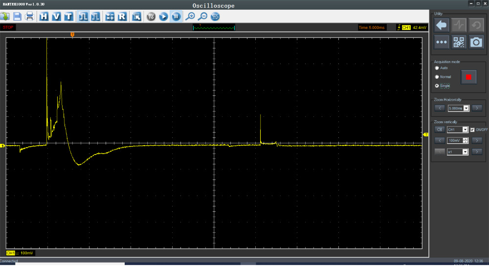
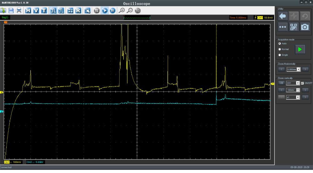
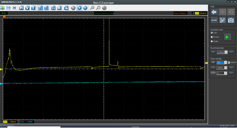
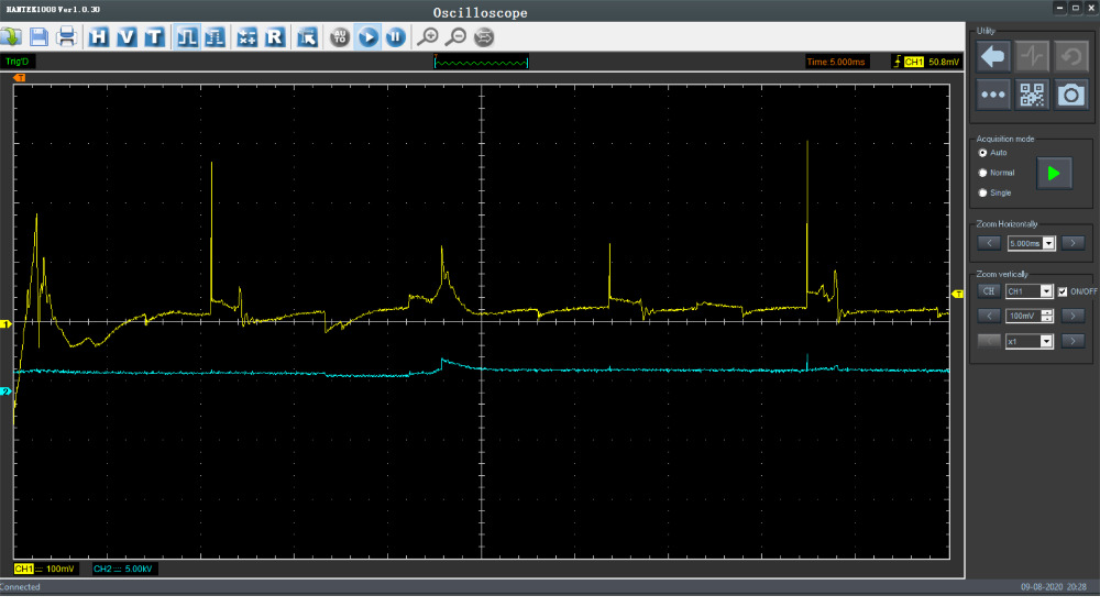
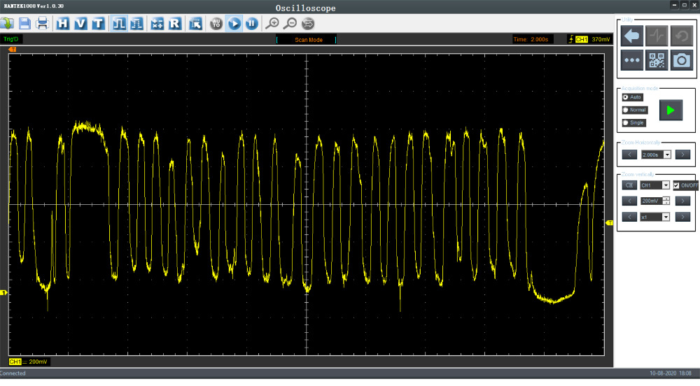
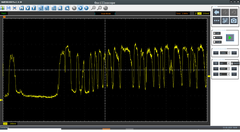
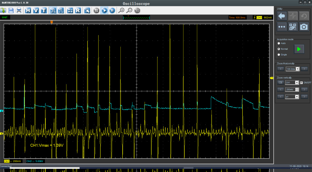
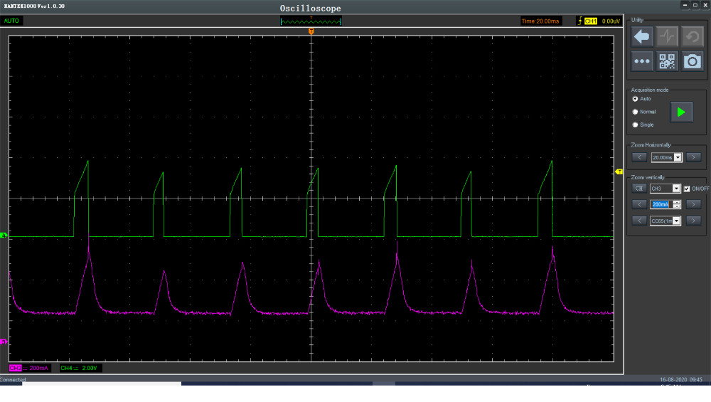
Some screenshots from my scope is attached. This is from one of the plug wires, but all 6 of them have a similar behavior. I can see that there is an ignition waveform buried in there, but there is a ton of spiking and really bad looking waveforms constantly coming in. Is this an indication of anything that you know of?
I was using a Hantek scope with an HT25 COP probe and holding it next to the plug wires. I'll be glad to get more screenshots if it would help. I used this same method with another truck that had Coil on plug igntion and it gave a good clean looking ignition waveform, so i don't think its a problem with my test equipment.
I'm just a guy trying to work on his own vehicle and i'll admit i still have a lot to learn, so i may be something simple that i'm missing.
Let me know if you've got any ideas.
Thanks

Please Log in or Create an account to join the conversation.
- guafa
-
- Offline
- Platinum Member
-

- Posts: 477
- Thank you received: 80
Are you snapping the throttle in those pictures?
Do you have frezze frame data? I mean, what were rpms when DTC was set?
Do you have fuel trims, IAC position, Map and others?
Can you describe which cylinder was scope and what are those traces?
The first picture looks like "No fuel misfire" but only if that was on snap throttle.
Please Log in or Create an account to join the conversation.
- mdce4
-
Topic Author
- Offline
- New Member
-
- Posts: 12
- Thank you received: 0
I attached some more pictures at other engine speeds.
When the DTC was set, the engine speed was idle, at 775 rpm.
STFT B1: 0.8%
LTFT B1: 9.4%
STFT B2: 1.6%
LTFT B2: -6.3%
MAF 0.78 lb/min
TPS 0%
IAT 144 F
Please Log in or Create an account to join the conversation.
- Donut
-
- Offline
- Senior Member
-

- Posts: 50
- Thank you received: 11
"Don't ever say 'easy' until the check clears."
Please Log in or Create an account to join the conversation.
- Donut
-
- Offline
- Senior Member
-
- Posts: 50
- Thank you received: 11
What do the trims do at 3k RPM?
"Don't ever say 'easy' until the check clears."
Please Log in or Create an account to join the conversation.
- mdce4
-
Topic Author
- Offline
- New Member
-
- Posts: 12
- Thank you received: 0
Here are the fuel trims at 3000 rpm:
STFT B1: 12.5%
LTFT B1: 9.4%
STFT B2: -13.1%
LTFT B2: -10.2%
IAT: 124F
TPS: 6.3%
MAF 2.95 lb/min
Spark adv: 43 deg
the hood was open during these readings.
Please Log in or Create an account to join the conversation.
- Tutti57
-

- Offline
- Platinum Member
-
- Posts: 1098
- Thank you received: 253
Nissan Technician
Please Log in or Create an account to join the conversation.
- Tyler
-

- Away
- Moderator
-

- Full time HACK since 2012
- Posts: 6120
- Thank you received: 1540
 I'd be tempted to do a relative compression test next.
 Please Log in or Create an account to join the conversation.
- mdce4
-
Topic Author
- Offline
- New Member
-
- Posts: 12
- Thank you received: 0
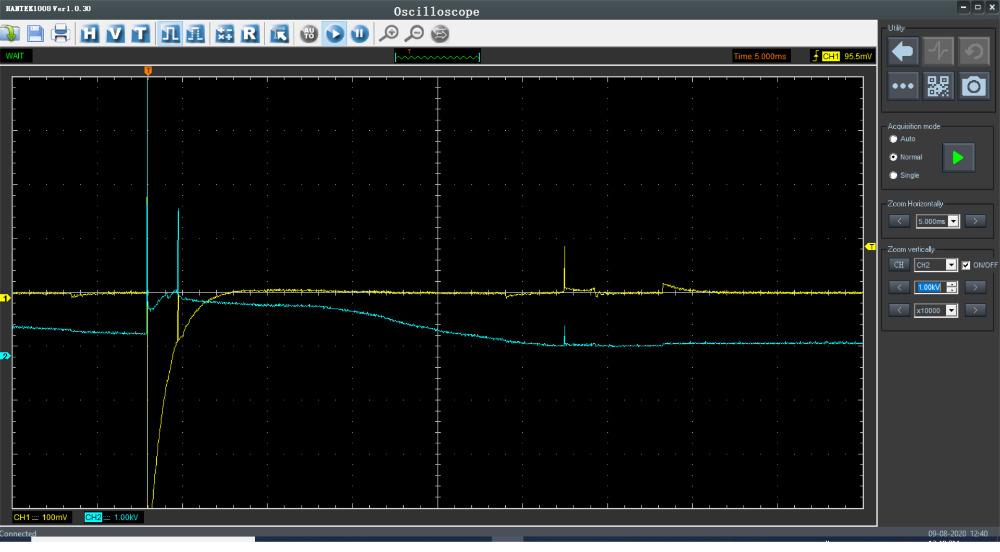
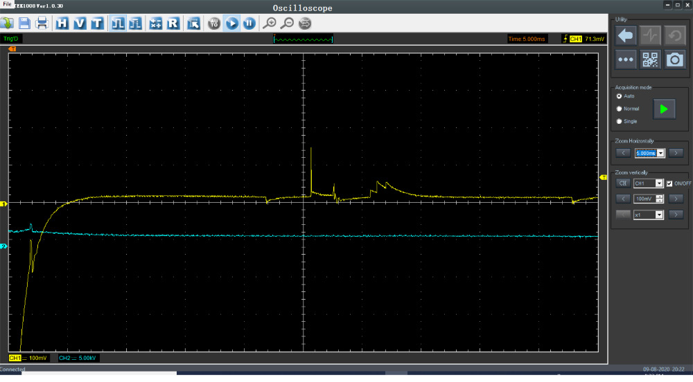
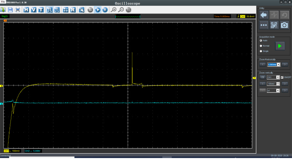
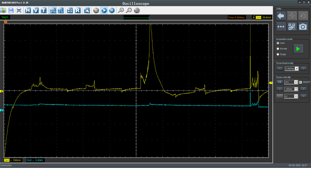
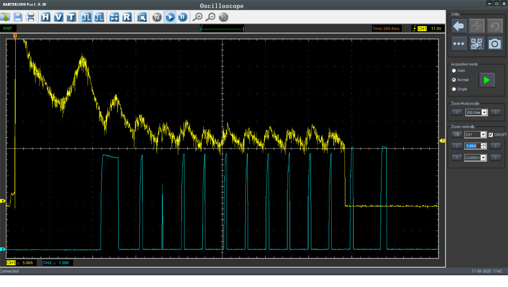
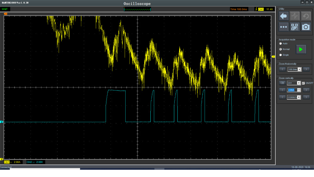
I did a relative compression test, see the picture. It seems ok to me, but let me know what you think.
Can the timing be checked with a scope? I don't have a timing light.
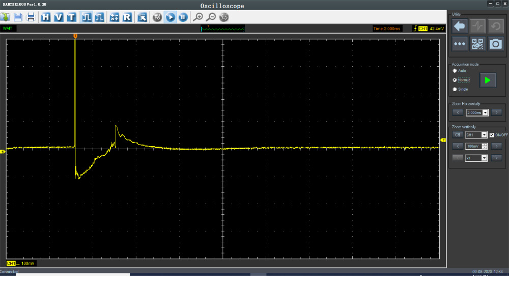
Also tried doing a snap throttle test of the ignition, but I don't know if this picture is of any use or not.
Please Log in or Create an account to join the conversation.
- Donut
-
- Offline
- Senior Member
-
- Posts: 50
- Thank you received: 11
You can check timing with a scope, and on these the cam sensor is in the distributor so it's up front and easy to get to. The crank sensor is buried in back, so less fun there.
I can't remember if it's a pain to get the upper timing covers off to check the timing on the cams, but that may be the most effective way to check timing in this case.
Did it run any differently after you replaced the plugs and fuel injector?
"Don't ever say 'easy' until the check clears."
Please Log in or Create an account to join the conversation.
- guafa
-
- Offline
- Platinum Member
-
- Posts: 477
- Thank you received: 80
Please Log in or Create an account to join the conversation.
- mdce4
-
Topic Author
- Offline
- New Member
-
- Posts: 12
- Thank you received: 0
Donut, when i replaced the injector and the plugs and wires, it ran a little better at first, but then it started getting the misfire again. I'm still trying to figure out how to check the cam and crank sensors, i'll let you know when i get a trend of that.
Please Log in or Create an account to join the conversation.
- Matt T
-
- Offline
- Platinum Member
-
- Posts: 751
- Thank you received: 276
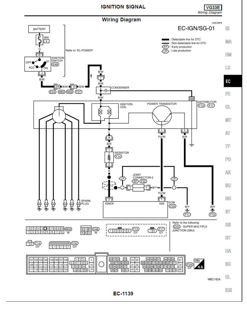
mdce4 wrote: I saw the video, but it doesn't say anything about if you can't get a good signal in the first place. On my signals, I seem to be getting a lot of interference from something. Maybe I'm doing something wrong. I couldn't figure out how to get the parade of all the cylinders together since the ignition coil and power transistor are located inside the distributor housing. I attached a drawing of ignition system, where should i connect my scope for this?
Moving your trigger higher so it only triggers on the firing kV of the lead you're on should help. That and separating the lead you're 'scoping away from the other leads helps with noise. That said you aren't going to get a secondary parade from that vehicle. You'll have to test each plug wire individually.
Looks like you might be able to get a primary voltage parade from the IGNCK wire on coil side of the resistor. That's if you've got a 20:1 attenuator.
Please Log in or Create an account to join the conversation.
- guafa
-
- Offline
- Platinum Member
-
- Posts: 477
- Thank you received: 80
Facts until now:
Code was set at normal temp operation and idling (no gaskets issue)
The more rpm you have, the more negative bank 2 goes and more positive bank 1 goes (bank 2 leading fuel control issue, bank 1 leading fuel delivery issue)
Fuel misfire neither ignition misfire, cause negative fuel trims (there is always more air detected by O2 sensors than expected)
Is one of the upstream sensors lying? what about swapping upstream O2 sensors?
Please Log in or Create an account to join the conversation.
- mdce4
-
Topic Author
- Offline
- New Member
-
- Posts: 12
- Thank you received: 0
I was able to get a trend of the cam and crank signals. They match what's in the service manual for idle and also at 2000 rpm. But this still doesn't answer the question for me about timing is correct or not.
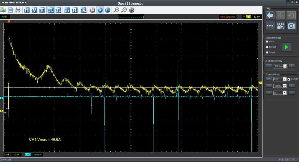
The amp peak value on primary side of coil was not the same for all cylinders, does this make a difference?
Here are the readings after swapping the upstream O2 sensors:
At idle:
STFT B1 -17.2
LTFT B1 9.4
STFT B2 12.5
LTFT B2 -2.3
At 2500 rpm:
STFT B1 -25
LTFT B1 9.4
STFT B2 25
LTFT B2 -10.2
Please Log in or Create an account to join the conversation.
- Donut
-
- Offline
- Senior Member
-
- Posts: 50
- Thank you received: 11
Your ignition timing looks alright. Considering Your compression doesn't have big dropouts and your spark appears to be near where it should be it doesn't look like your mechanical timing is off any.
"Don't ever say 'easy' until the check clears."
Please Log in or Create an account to join the conversation.
- guafa
-
- Offline
- Platinum Member
-
- Posts: 477
- Thank you received: 80
As Donut mentioned. If nothing else changed, i would call for new O2 sensors (because both are reacting in the same way no matter where they are).
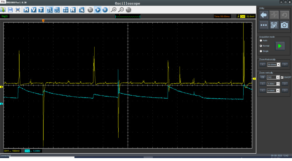
Second picture is for voltage (Green trace) and current (violet trace) at ignition control wire? Same question about blue trace in first picture. Is it voltaje or current trace?
Please Log in or Create an account to join the conversation.
- mdce4
-
Topic Author
- Offline
- New Member
-
- Posts: 12
- Thank you received: 0
These are original O2 sensors as far as i know.
I zoomed in a little more for the compression test. The IGN signal (light blue) is voltage with an amplitude of about 4V.
On the other picture, the green was voltage (IGN control wire), and the purple was amps (blue wire #8 between resistor and ignition coil/transistor.)
Please Log in or Create an account to join the conversation.
- guafa
-
- Offline
- Platinum Member
-
- Posts: 477
- Thank you received: 80
About O2 sensors, you have proved that both circuit integrity are fine.
For O2 sensor test, you don´t need to move any of the connectors from where they live. Just unplug connectors, unbolt the sensors and swap them.
Edit: Do you mean sensor wire? ok. yes then. you have to extend wires (be careful).
Please Log in or Create an account to join the conversation.
- guafa
-
- Offline
- Platinum Member
-
- Posts: 477
- Thank you received: 80
If you make a vacuum leak PCM Will respond adding fuel because you create a lean condition. If O2 sensors are ok, both banks STFT should go more positive (bank 2 less negative).
With engine running, also you can unplug injectors one by one on bank 2 (the rich one) and keep an eye on STFT. if there is a leaking injector, you should see a noticeable change.
Please Log in or Create an account to join the conversation.