04 chevy Silverado hvac issue
- Thrashnasty13
-
 Topic Author
- Offline
- Senior Member
-

- Posts: 69
- Thank you received: 9
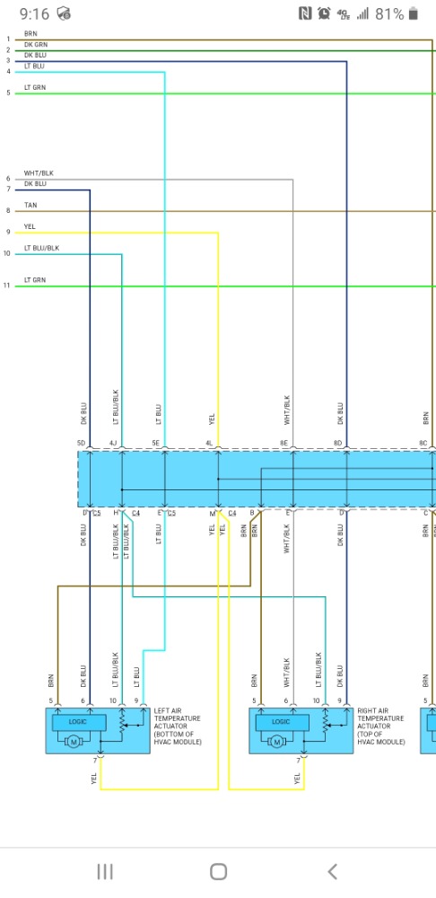
Pin 5 (brown wire) -12v
Pin 6 (dk blue) - control
Pin 9 (Lt blue) - control
Pin 10 (Lt blue/blk) - 5v reference
Pin 7 (yellow) - low volt reference (I'm assuming ground?)
Can anyone clarify how this operates? I looked at the description in identifix but it wasnt much help. Trying to be proactive before working on this truck. Thanks
Please Log in or Create an account to join the conversation.
- jreardon
-
- Offline
- Platinum Member
-

- Posts: 521
- Thank you received: 198

Please Log in or Create an account to join the conversation.
- Thrashnasty13
-
Topic Author
- Offline
- Senior Member
-
- Posts: 69
- Thank you received: 9
Please Log in or Create an account to join the conversation.
- ScannerDanner
-

- Offline
- Administrator
-

- Religion says do, Jesus says done!
- Posts: 975
- Thank you received: 500
2 wire reverse polarity DC motor
Low ref is the sensor ground circuit
Don't be a parts changer!
Please Log in or Create an account to join the conversation.
- Cheryl
-
- Offline
- Platinum Member
-
- Posts: 1216
- Thank you received: 215
Please Log in or Create an account to join the conversation.
- Thrashnasty13
-
Topic Author
- Offline
- Senior Member
-
- Posts: 69
- Thank you received: 9
Please Log in or Create an account to join the conversation.
- Thrashnasty13
-
Topic Author
- Offline
- Senior Member
-
- Posts: 69
- Thank you received: 9
Please Log in or Create an account to join the conversation.
- Thrashnasty13
-
Topic Author
- Offline
- Senior Member
-
- Posts: 69
- Thank you received: 9
Few questions here for the guys with more knowledge than I.
1. Did I diagnose this right the first time and the second time, and is there anything that im missing?
2. Focusing on the actuators, how does the control circuit operate? what does the control module send down that control wire to the actuator? Is it a signal and the actuator motor uses the 12v, 5v ref and ground the move or does the control wire actually carry a load?
3. The potentiometer is used as a feedback loop so the HVAC control module knows the actual position of the actuator. However does this circuit have control to keep the module from moving the actuator down the control wire or is it just a simple feedback loop?
Sorry for any confustion in my post I tried to explain my thoughts and process. Im in the process of reading pauls book and following along with the videos but im not very far in it and had this issue come into the shop so i dove head first into it.
Please Log in or Create an account to join the conversation.
- jreardon
-
- Offline
- Platinum Member
-
- Posts: 521
- Thank you received: 198
The "feedback" circuit, aka this potentiometer circuit, is ENTIRELY the basis for code setting. When the HVAC module first gets powered up it will check this "feedback" circuit at each actuator for proper range of motion (self calibration) and can disable the actuator from moving again until next key cycle if something's not quite right. This means if the HVAC can't monitor where the door is at, it might not move it. Don't condemn the HVAC without checking this signal wire.
The HVAC monitors the voltage on the signal wire and converts it into "counts" as displayed on the scan tool. (see image). Scope the signal wire, turn the key on and off, or run the self calibration test in scanner, and see if the signal voltage is nice and smooth like in a TPS sweep test. No dead spots!
These three wires (constant 5v, constant 0v ground, and changing signal voltage from motor movement) are identical in operation to a TPS test:

Please Log in or Create an account to join the conversation.
- jreardon
-
- Offline
- Platinum Member
-
- Posts: 521
- Thank you received: 198
That's odd, I thought these voltages were discrete. Check your meter ground.Thrashnasty13 wrote: I back probed both right and left blend door actuators on the control wires several different times and found different resting voltages from 1.9v to 2.8v, never the norm of 2.5v.
In the end what matters most is do these actuators move or not when commanded? Do they have codes? Maybe the actuator is fine with that voltage for resting voltage. If it's a problem then I would cut the wire and see if this voltage returns to expected 2.5V and might be affected by a faulty actuator.
Please Log in or Create an account to join the conversation.
- jreardon
-
- Offline
- Platinum Member
-
- Posts: 521
- Thank you received: 198
Lol, I hope you're not saying you have 12v on all those 3 wires, because if you do then you have a bad ground. Also put the first HVAC back in, the replacement sound like it's more trouble than it's worth.Thrashnasty13 wrote: I forgot to mention earlier but the other wires at the actuators always had 12v on the brn wire, 5v ref and low referance.
Please Log in or Create an account to join the conversation.
- Thrashnasty13
-
Topic Author
- Offline
- Senior Member
-
- Posts: 69
- Thank you received: 9
Please Log in or Create an account to join the conversation.
- Thrashnasty13
-
Topic Author
- Offline
- Senior Member
-
- Posts: 69
- Thank you received: 9
So a signal wire from the actuator not matching the commands by the modules will keep the module from controling the actuator. Also I read useing a jump wire to use battery negative was acceptable, would that be the same with using the ground side on a power probe hook connected to the battery?
Please Log in or Create an account to join the conversation.
- Thrashnasty13
-
Topic Author
- Offline
- Senior Member
-
- Posts: 69
- Thank you received: 9
Please Log in or Create an account to join the conversation.
- Thrashnasty13
-
Topic Author
- Offline
- Senior Member
-
- Posts: 69
- Thank you received: 9
I checked the ground on the left one and it had 40-60 mV on a volt drop test with the circuit loaded.
Also I can still not communicate with the new hvac controller with data I can see the codes (their are none). With the old module I can go into every setting on my scanner. Even now if I plug the old one in I have total control. Both new ones haven't let me communicate with the data.
Please Log in or Create an account to join the conversation.