2005 f 150 4.6 has -20% LTFT'S on both banks
- Patrickreaves
-
 Topic Author
- Offline
- Senior Member
-

- Posts: 62
- Thank you received: 25
Scanner John , After testing again , I found that pulling the vacuum line on the FRP sensor actually had no effect on the fuel pressure reading at all. it was when i unplugged the sensor that it went to 75 psi, (sorry about that). I'm not sure what the vacuum line is for, i thought it worked like a regulator, full-vacuum = Idling/no load, and no-vacuum=WOT/under load?? (I'm not sure) or maybe its a "clue", that my fuel pressure did not change when i removed it.
I watched Scanner Danner test a similar FPDM on a 2002 Taurus, titled (ford electronic returnless fuel pump), his readings were different than mine and more like you described. His 2 second prime was a 50% duty cycle , then went to 25 % after the prime was over, and back to 50% during cranking. His on/off square wave signal also matched the duty cycle reading. 25%=pump off/no ground applied, 50%=pump on/full ground applied, and his car was a no start so i don't know what the percentage would be with engine running.then on another ford video with the engine running (pic below) he guessed the on time /duty cycle to be about 20%. i did the exact test with the exact same scope,(vantage mt 2400) and my vantage pro. but my duty cycle command was 50 % all the time just like you suggested and the square wave signal also showed this and did not change (as Danners did). so maybe you are on to something. I will test again later. then going through my scan data pids, I found the data pid for Duty Cycle % and it read the opposite as Danners. It read, 2 second prime/cranking=50%, then after the prime was over/pump off=75%, engine at idle=32%, and WOT=50%
?
Please Log in or Create an account to join the conversation.
- Patrickreaves
-
Topic Author
- Offline
- Senior Member
-
- Posts: 62
- Thank you received: 25
Att#1 prime /crank/WOT =47%
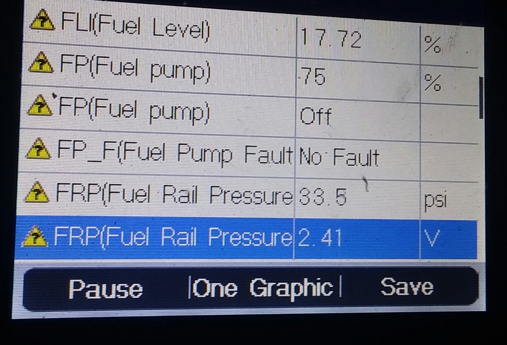
Att#2 pump off after prime =75%
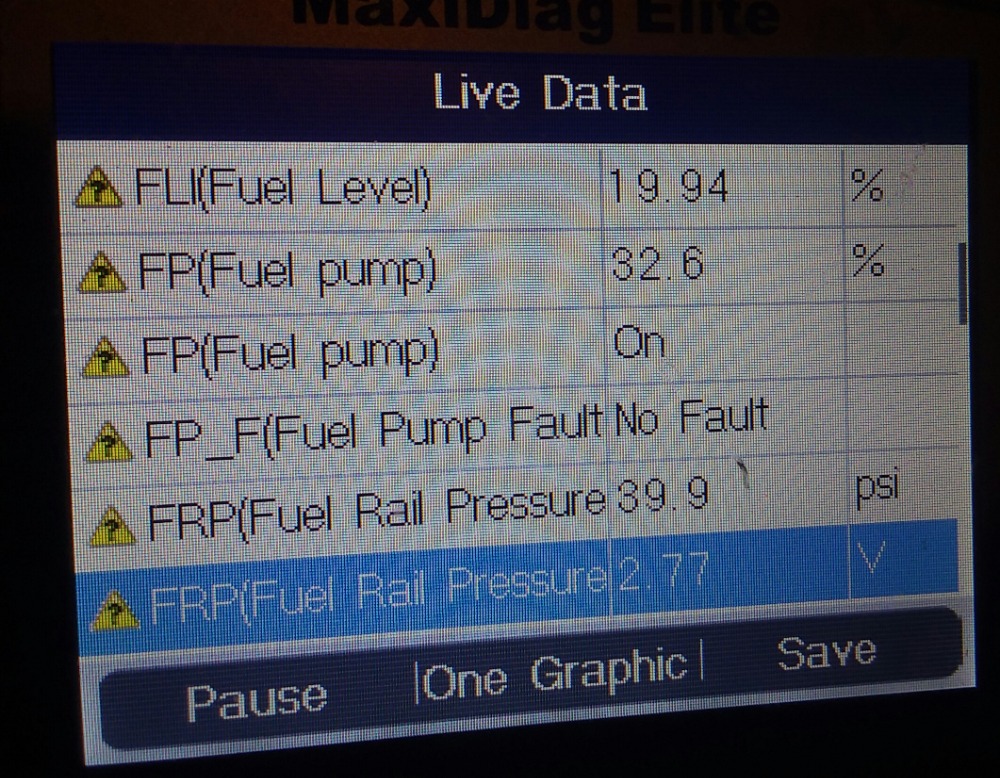
Attj#3 engine running =32%
Att#4 pid information

Please Log in or Create an account to join the conversation.
- kwak208
-
- Offline
- New Member
-

- Posts: 1
- Thank you received: 1
Please Log in or Create an account to join the conversation.
- Patrickreaves
-
Topic Author
- Offline
- Senior Member
-
- Posts: 62
- Thank you received: 25
thanks for the suggestion.
Please Log in or Create an account to join the conversation.
- VegasJAK
-

- Offline
- Platinum Member
-

- Silencing the Parts Cannon
- Posts: 566
- Thank you received: 140
as Tyler said, "That's the feedback signal from the FPDM to the PCM, and it'll only change if the FPDM detects an issue. An 'issue' results in the duty cycle going to zero or 100%"
It has not set a code yet, but an issue exists... my opinion.
Its a pain but you might want to check the FPD module itself. The base is aluminum and Ford mounted it on the steel cross member above the spare tire. Aluminum and steel do not mix, it causes the aluminum to oxidize. Ford fixed this by using mounting bolt stand offs with plastic washers to attach the module and an anti oxidizing paste to the back of the module.
"an open mind let's knowledge flow in and wisdom flow out for a man who has neither never listens to those who have both".
Please Log in or Create an account to join the conversation.
- Patrickreaves
-
Topic Author
- Offline
- Senior Member
-
- Posts: 62
- Thank you received: 25
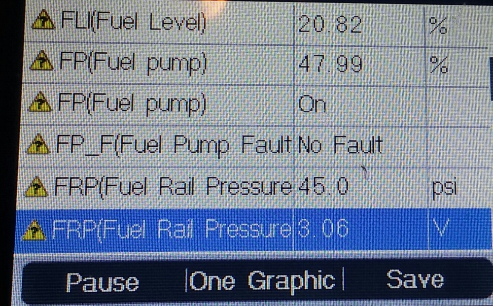
I connected 2 different style fuel pressure gauges, and at idle it has 36 psi, then shoots up to 45 psi during WOT. When I remove the vacuum line it also goes up to 45 psi. I believe this is working correctly. My scan tool read 40 psi with, and with out the vacuum line on it.(not sure why).when i un plug the FRP sensor connector, the fuel pressure falls to 20 psi.(limp mode strategy). And finally, during the hesitation on take off, there is a steady 45 psi on the gauge. so fuel pressure looks good to me and has nothing to do with the hesitation.
The timing is where i seen an issue during the hesitation. in park at 700 rpms( Timing/Advance hovers at 8-10 degrees. at 1500 rpm=15 degrees T/A , at 2500 rpm= 25 degrees T/A, at 3500 rpm=30 degrees T/A.
while driving normally, timing advance hovers between 10-15 degrees , under heavy load/ kick down/( pushing you into the seat) 2000-4000 rpms the timing advance stays very near 10 degrees.
in 1st gear/ reverse, during hesitation(1600 rpms) ,timing advance is -5 to -7, (thats a 15-20 degree difference from the other two test control numbers above) The issue, is that the engine WILL NOT rev passed 1600 rpms if under 8 mph. After 8 mph it will rev up to max rpm with no problem. (thoroughly tested) so thats why its so sluggish , rpm is held steady at 1600 rpms untill i surpass 8 mph. cant spin a tire while going up hill in grass, limerock , dirt, gravel, pavement. and it doesn't take off fast because rpm is being limited to 1600, no matter how far i push the gas peddle
a few times it actually revved to 1800 rpms and then fell back down to 1600 rpms with peddle to the bottom, and held there until 8mph. The rpm falling back to 1600 is what is creating the feeling of hesitation/ no response/slowing down/no power. After 8mph no problem.
Please Log in or Create an account to join the conversation.
- Patrickreaves
-
Topic Author
- Offline
- Senior Member
-
- Posts: 62
- Thank you received: 25
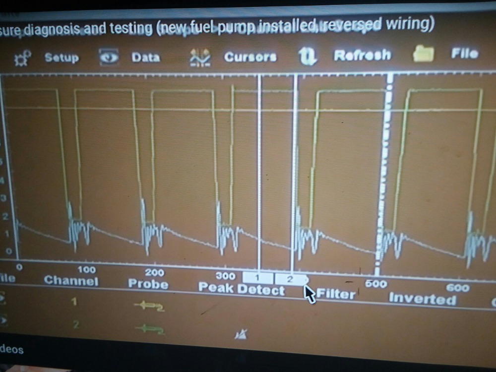
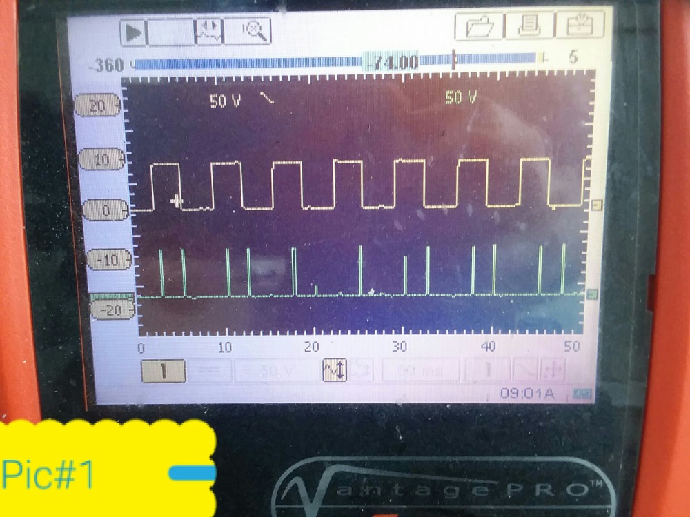
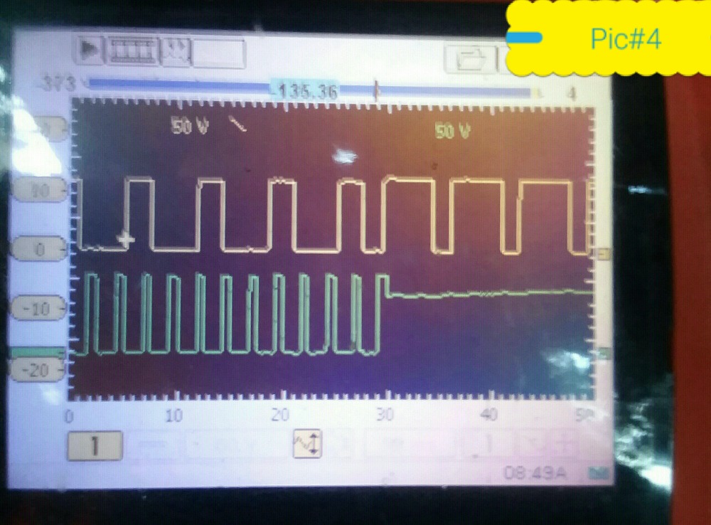
Im on a 50 volt scale because it was the best way to get both waveforms in the capture. The lower portion should be the on time, and upper portion being the off time.
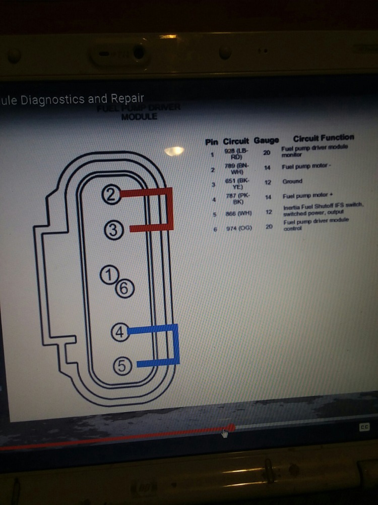
pic #1 CRANKING with 50% duty cycle = yellow trace is on pin # 6 of diagram (module control) and green trace is on pin # 2 (pump ground)/ FPDM applied ground. this wire has 12 volts with key off,(pump contacts good).. During cranking it has a full ground. (this was the same as danners )
Leads connected the same for all pics.
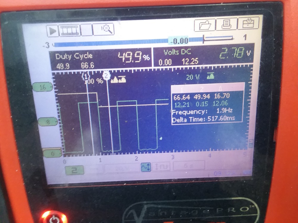
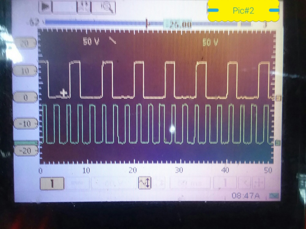
pic #2 and #3-- engine running at idle, shows 68.6% duty cycle command (danners video showed 20% on the green trace (applied ground) with the engine running. After capturing pic #2, I left my leads connected and went to duty cycle on my vantage pro , and captured pic #3. ' ( I'm not sure why duty cycle is at 68% command, and 63% actual. (this would suggest that the pump is being grounded 70% 0f the time , (when max is supposed to be 50%), but then I don"t have excessive fuel pressure).
pic #4 is where the engine was running 70% duty cycle on the left side of capture, and on the right side is where i shut the key off and it returned to 25 % duty cycle command on the yellow trace, and the green trace has the curve effect from counter electromotive force as it climbs back to 12 volts . (the return to 25% duty cycle with the key on/pump off, should be normal, and is like the 2 cars that scanner danner checked. but that 70% command does not look right to me, as it should be closer to 20-30% with the engine running.
edit=
I also disconnected the FPDM about 4 times and let it run until it died, to relieve the fuel pressure, so i could install my fuel pressure gauges. Research says that it should, but may or may not flag a trouble code for (1) loss of communication (,2) if fuel pressure is less than 20 psi, and( 3) if pressure is greater than 60 psi. I have met all those conditions and it has never flagged a code. Research said that when a pump wears out it will require MORE average voltage (longer duty cycle ) to keep up with pressure demands. My fuel pump being worn out , would support the longer duty cycle of 70%
Please Log in or Create an account to join the conversation.
- VegasJAK
-
- Offline
- Platinum Member
-
- Silencing the Parts Cannon
- Posts: 566
- Thank you received: 140
My original theory was the duty cycle was fixed at 50%(full on) on the command line therefore providing too much fuel between start and WOT. The FRP sensor should see this and report the incorrect pressure.
"an open mind let's knowledge flow in and wisdom flow out for a man who has neither never listens to those who have both".
Please Log in or Create an account to join the conversation.
- Patrickreaves
-
Topic Author
- Offline
- Senior Member
-
- Posts: 62
- Thank you received: 25
my pressure is in spec so the pump is staying.
what I dont understand is , that if 50% duty cycle is a full ground, then anything over 50 % should still be a full ground. on my capture above 70 % does not equal a full ground as seen in wave form. it may be that duty cycle commands with the engine off, are not the same / equivalent as duty cycle commands with the engine running. that is the only thing that makes sense to me.
like you said , maybe someone with more knowledge on this subject can shed light on it
Please Log in or Create an account to join the conversation.
- VegasJAK
-
- Offline
- Platinum Member
-
- Silencing the Parts Cannon
- Posts: 566
- Thank you received: 140
5 to 45% This is a normal operating range. ***The FPDM will operate the fuel pump at the speed requested***. When the FPDM sees this signal, it will run the fuel pump twice the speed of the signal. For example, 30% duty cycle from the computer the FPDM will run the fuel pump at 60%. The FPDM will send a duty cycle signal back to the PCM of 50% indicating everything is functioning properly.
48 to 51% Normal operation. ***The FPDM will operate the fuel pump at 100%***. FPDM will send a 50% duty cycle signal back to the PCM on the FPM circuit indicating everything is functioning properly.
70 to 81% the PCM will send this signal to the FPDM ***when it requests the fuel pump off***. ***The FPDM will "not" operate the fuel pump*** and FPDM will send a 50% duty cycle signal back to the PCM on the FPDM circuit indicating is functioning properly.
"an open mind let's knowledge flow in and wisdom flow out for a man who has neither never listens to those who have both".
Please Log in or Create an account to join the conversation.
- Patrickreaves
-
Topic Author
- Offline
- Senior Member
-
- Posts: 62
- Thank you received: 25
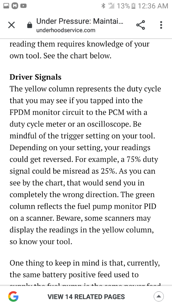
The only thing that makes sense now is that my duty cycle signal is actually inverted on my scope. (This would now be a 30% duty cycle instead. And the write up said that this very thing could happen. I will attach that portion below
You said that if every thing is working correctly that the FPDM will send a 50% duty cycle on monitored return line, and thats exactly what ive got with engine running.
But really. Thanks for pointing this out, as the FPDM' works differently from how i originally thought that it did.
Please Log in or Create an account to join the conversation.
- VegasJAK
-
- Offline
- Platinum Member
-
- Silencing the Parts Cannon
- Posts: 566
- Thank you received: 140
so, I guess we are back to the start... what is causing your rich condition.
fuel pressure (pump or regulator)
induction over measured (MAF/MAP)
fuel leaks (injectors)
02 sensors
EGR
PCV
coolant temp sensor
EVAP
I know you have done many of these all ready, but the condition continues, soooo...
"an open mind let's knowledge flow in and wisdom flow out for a man who has neither never listens to those who have both".
Please Log in or Create an account to join the conversation.
- Patrickreaves
-
Topic Author
- Offline
- Senior Member
-
- Posts: 62
- Thank you received: 25
"Returning to returnless fuel systems in the ford f150" is another good write up, and the one I originally read first. (still good info)
Today i raised the injectors up and out of the intake one bank at a time. No leaks were present after multiple primes and 40 psi on gauge. I then Placed measuring cups under each injector and disconnected the coils on the same bank. (remembering scanner Danner emphasizing that intentional shut down does not accur during start up, and that start up is when a driver will turn the injector back on). I then cranked the engine and it started and died after 5 seconds. checked to find that cups where empty. "huh' I then plugged all coils back in and cranked again. STILL NOTHING in the cups. I then checked to find no codes in memory, but reset KAM anyways. cranked and started (running poorly) for 5 seconds, and there was no fuel spray at all, into the measuring cups. After repeatedly starting the truck, the injectors never sprayed a drop. the 40psi fuel pressure did blow an injector out of the rail a few times. (this let me know that fuel was making it to the nozzles)
I have done this procedure before on another cars. not sure why i got these results.
while i had the fuel rail out, I replaced all 8 injectors from another 2005 4.6 f150. With the keep alive memory reset, the fuel trims had to relearn and settled right back close to -20 % on the long terms for both banks. with these results i think i can scratch injectors off the list.
when i bought this truck a year ago the intake gasket was badly ruptured between the intake runner and a coolant port. this was my diagnosis as there was steam coming out the exhaust non stop, and the coolant system would not pass a coolant pressure test at the resorvoir. I completed the repair, and fixed both symptoms. how ever, the - 20% LTFT's has never gone away . and am now leaning toward the 02's being skewed from water/steam contamination. when i changed the 02''s, all i did was rotate the down stream 02's with the up streams. and after thinking about it, they are probably contaminated also.
Please Log in or Create an account to join the conversation.
- Patrickreaves
-
Topic Author
- Offline
- Senior Member
-
- Posts: 62
- Thank you received: 25
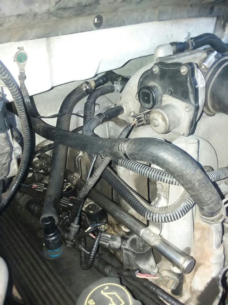
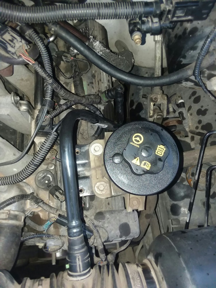
I also changed the up stream oxygen sensors today with no effect on trims. will post a picture .
my LTFT's are -20 to -24%. however, the ONLY THING I have found to have an improvement on trims is by completely blocking off the two PCV lines, which removes all vacuum to the crank case. I never explored further because i was under the impression that crank case vapors are supposed to be pulled out and back into the intake , and that the pcm has calculated these vapors into the 14.7 to 1 air /fuel ratio. and if this is true, blocking the pvc lines off on a good running engine will cause a lean condition. If this is true, then the improvement that i am seeing is not valid, as i have only taken away a portion of the calculated mass air.
Fuel trims are now close to -10% on the LTFTs
But I am not certain, that this is correct.
All knowledge is appreciated. thank you
Please Log in or Create an account to join the conversation.
- VegasJAK
-
- Offline
- Platinum Member
-
- Silencing the Parts Cannon
- Posts: 566
- Thank you received: 140
if you have an air leak in the PVC system, MAP voltage will be high and the PCM will think the engine is at a higher load so it will add fuel and retard spark.
you reported a calculated load value of 25-30% at idle which is high. most ford 4.6 owners say they have around 16, but I think that high as well. your MAP of 5.1 psi is a little over 10hg. Should be 6 or so... voltage should be .5 to 1.5 at idle.
MAP and MAF are different... MAF measures the air coming into the throttle body, MAP monitors the pressure in the intake. a vacuum leak will make the MAP read high and not effect the MAF reading (directly).
if the MAP is reporting the engine under load then the PCM will signal the FPDM to turn on (ground) the fuel pump longer for a greater fuel demand... fuel pressure stays at that 40psi, but the pump runs full or longer to keep up with demand.
I think your almost there... keep us posted.
"an open mind let's knowledge flow in and wisdom flow out for a man who has neither never listens to those who have both".
Please Log in or Create an account to join the conversation.
- Tutti57
-

- Offline
- Platinum Member
-
- Posts: 1098
- Thank you received: 253
Nissan Technician
Please Log in or Create an account to join the conversation.
- Patrickreaves
-
Topic Author
- Offline
- Senior Member
-
- Posts: 62
- Thank you received: 25
in gear at idle (700 rpm) = 40% load
in gear at idle wit A/C on = 45% load
yes scanner john, I think your right. I think calculated load is way too high. These numbers have always bothered me! It jumps up to 100% load with 20%peddle applied.
As to PCV lines, bank 1 line goes to intake manifold,(has as much vacuum as the brake booster line.) seems it would suck up oil.
Bank 2 line goes to air duct, behind MAF sensor. I blocked off the 2 pcv lines, and put a vacuum gauge on the dipstick as "nissan tech" suggested. No vacuum in crankcase, but there was .5 psi of pressure.
So my oil may be fuel contaminated, (and I have heard that an oil change will fix negative trims if contaminated) But i have changed my oil multiple times in the last year,( expecting an improvement)and have never seen an improvement on trims after the fact. I will retest to be 100% sure.
Other than all i have done , I am out of directions to go, I have to be missing something.
To everyone, who has kept up with this, super long thread, and have shared information and suggestions with me, Thank You, I really appreciate you guys.
Please Log in or Create an account to join the conversation.
- Tutti57
-
- Offline
- Platinum Member
-
- Posts: 1098
- Thank you received: 253
Nissan Technician
Please Log in or Create an account to join the conversation.
- Patrickreaves
-
Topic Author
- Offline
- Senior Member
-
- Posts: 62
- Thank you received: 25
I drove a perfectly fine 2007 f150 4.6 today and looked at its data parameters for comparison. Coolant temp was 207 degrees. 17 degrees hotter. So ill take the advice and get a hotter thermostat right now. Will post results soon. Thanks
and i wish this site would stop rotating the pics i post, i have to crop them and turn them before i post so they show up correct. lol
Please Log in or Create an account to join the conversation.
- Tutti57
-
- Offline
- Platinum Member
-
- Posts: 1098
- Thank you received: 253
Nissan Technician
Please Log in or Create an account to join the conversation.