Causing open loop fault, MAF 100lb/sec
- Otbrecords
-
 Topic Author
- Offline
- Senior Member
-

- Posts: 52
- Thank you received: 13
Please Log in or Create an account to join the conversation.
- Otbrecords
-
Topic Author
- Offline
- Senior Member
-
- Posts: 52
- Thank you received: 13
MAF 100 lb/sec
TPS. 15.3%
02SB1S1 0.855v
STFTB1S1 99.2%
OBD SUP OBDII
LAMBDA B1S1 1000
O2S B1S1 3.298V
CALC LOAD 49.4%
VEH SPEED 0 (MPH)
ECT 178 (*F)
ENG RPM 552 ( at idle)
STFT B1 0.0%
LTFT B1 0.0%
SPARK ADV. 9.0 (*)
IAT 66 (*F)
O2SLOC O2SII & O2S12
The truck had warmed up for 15 minutes and was idling when this live data was recorded. I'm wondering what is causing my open loop fault.
As usual I appreciate your help and any time that you put into this with me.
Please Log in or Create an account to join the conversation.
- John Curtis
-
- Offline
- Platinum Member
-

- Posts: 345
- Thank you received: 111
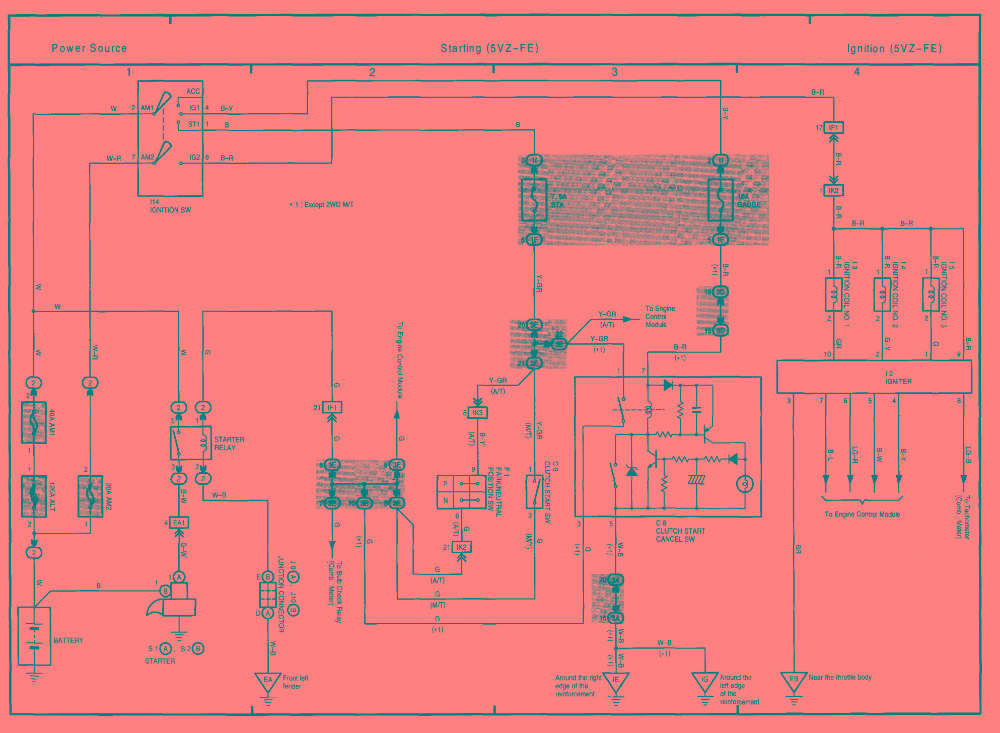
That would be significantly over reporting.
I would suggest fixing your spark issue first... here is a diagram if you need it.
Making Pressure Differential Sensors (PDA Sensors) for pressure pulse diagnostics.
Currently servicing Central Texas.
Please Log in or Create an account to join the conversation.
- jreardon
-
- Offline
- Platinum Member
-
- Posts: 521
- Thank you received: 198
Otbrecords wrote: The truck had warmed up for 15 minutes and was idling when this live data was recorded. I'm wondering what is causing my open loop fault.
P0031 is a heater code
From www.scannerdanner.com/forum/diagnostic-t...-thread.html?start=0
Tyler wrote: 2.) Heaters are not optional
The majority of conventional O2’s are still capable of producing a decent signal with a blown heater element, provided the exhaust is hot enough. Not the case here. The heater HAS to be functioning, or the sensor will never work correctly. In fact, some vehicles will default to open loop fuel control with the presence of a heater fault.
As for the no spark, try the ScannerDanner bypass test: key on (powers up the coils and ignitor), backprobe at the ignitor on the IGT1 wire, touch backprobe with incandescent test light connected to battery positive and watch for spark at either #1 or #4 plug boot to ground.
If this works, then your ignitor and coil is fine. Focus goes to wiring to computer, or computer problem. I'm not sure if cam or crank would be suspect as you have spark on other cylinders and you have no cam or crank codes. It's got to be a wiring problem or computer problem I think.
Please Log in or Create an account to join the conversation.
- Otbrecords
-
Topic Author
- Offline
- Senior Member
-
- Posts: 52
- Thank you received: 13
Please Log in or Create an account to join the conversation.
- jreardon
-
- Offline
- Platinum Member
-
- Posts: 521
- Thank you received: 198
Please Log in or Create an account to join the conversation.
- Otbrecords
-
Topic Author
- Offline
- Senior Member
-
- Posts: 52
- Thank you received: 13
Please Log in or Create an account to join the conversation.
- Otbrecords
-
Topic Author
- Offline
- Senior Member
-
- Posts: 52
- Thank you received: 13
Please Log in or Create an account to join the conversation.
- jreardon
-
- Offline
- Platinum Member
-
- Posts: 521
- Thank you received: 198
Otbrecords wrote: I put it all back together and back probed IGT1 at the PCM harness as well as IGT2 for comparison with engine on. IGT2 is pulsing at 3.9 volts and IGT1 has 0 volts.
That's good you did that check at the PCM harness. Now, was it 0 volts because the wire was shorted? Connect a test light to battery positive and touch the wire. If it lights you have a short to ground.
While you're there, If you can make the ignitor fire the coils at the ignitor connector, but not at the pcm harness, then it's a wire problem.
As far as I know from ScannerDanner's videos, only the injectors get shut down to save the catalytic converter.
Please Log in or Create an account to join the conversation.
- Otbrecords
-
Topic Author
- Offline
- Senior Member
-
- Posts: 52
- Thank you received: 13
On a side note I back probed all four wires of A/F sensor B1S1 (2 black 1 white 1 blue wire) Here's what I got.
Key on - 12v on both black wires, other two had 3.3v & 3.0v
Key off - All 4 wires went to ground. Continuity between black wires only.
I think I'm going to throw my first part at this issue.. A new A/F sensor. Thoughts?
Thanks you Jreardom for the direction and education. I appreciate all the help from everyone.
Please Log in or Create an account to join the conversation.
- jreardon
-
- Offline
- Platinum Member
-
- Posts: 521
- Thank you received: 198
Otbrecords wrote: Using positive test probe on all ITGs at ECU makes test probe light up but barely.
Okay so your test light is finding a ground through the computer maybe and that's normal. I can't let go of a hunch that this wire is touching ground somewhere intermittently when the engine shakes during the misfire, causing this signal to get pulled to ground.
Disconnect the Ignitor and the ECU. I'm interested in only one wire and I want you to check for an intermittent short to ground. Rig up your test light to battery positive and connect to any end of this IGT1 wire that's easiest to get to. Then I want to you slowly and gently push down on the harness everywhere you can see where the harness contacts metal. If the test light lights that indicates a short.
Please Log in or Create an account to join the conversation.
- Cheryl
-
- Offline
- Platinum Member
-
- Posts: 1216
- Thank you received: 215
Please Log in or Create an account to join the conversation.
- John Curtis
-
- Offline
- Platinum Member
-
- Posts: 345
- Thank you received: 111
Otbrecords wrote: Ok I back probed IGT1 at ECU harness and was able to trigger coil. Sweet! ITG's on 03 Tacoma are "pull up" triggered. Consequently having a negative polarity with key on. Using positive test probe on all ITGs at ECU makes test probe light up but barely.
On a side note I back probed all four wires of A/F sensor B1S1 (2 black 1 white 1 blue wire) Here's what I got.
Key on - 12v on both black wires, other two had 3.3v & 3.0v
Key off - All 4 wires went to ground. Continuity between black wires only.
I think I'm going to throw my first part at this issue.. A new A/F sensor. Thoughts?
Thanks you Jreardom for the direction and education. I appreciate all the help from everyone.
When it comes to 02 or AF sensor codes whenever it is a “heater circuit code” it is pretty accurate.
Something to consider though, while you were on the right track at testing the 2 black wires, you should be testing to measure resistance. A continuity test (I believe) if confirmed to have continuity will tell you that the circuit has 50 OHMS or less. 02 and AFrs should be 5 to 10 OHMS.
Making Pressure Differential Sensors (PDA Sensors) for pressure pulse diagnostics.
Currently servicing Central Texas.
Please Log in or Create an account to join the conversation.
- Otbrecords
-
Topic Author
- Offline
- Senior Member
-
- Posts: 52
- Thank you received: 13
Please Log in or Create an account to join the conversation.
- Otbrecords
-
Topic Author
- Offline
- Senior Member
-
- Posts: 52
- Thank you received: 13
I'm fairly certain, as certain as one with my limited skill can be, that the A/F sensor is causing my open loop fault and possibly other things. Before I try a junkyard part or eventually new one, opportunity presents itself to learn something. The continuity between both black wires went to zero which if I understand is not what I want correct? How should I test it and what am I looking for exactly?
On a side note out of curiosity. My vacuum gauge test showed around 10 inches of mercury indicating a timing issue. Even though all marks are lined up and discounting a sheared key pin on crankshaft gear. I'm assuming that this no spark would cause the same vacuum symptoms? Since this all started after GFs brother replaced timing belt and knowing a torque wrench was not used. It's in the back of my mind whether or not vacuum is an issue because of a shifted gear. I observe no wobble in pulley but doesn't stop me from wondering.
Please Log in or Create an account to join the conversation.
- Andy.MacFadyen
-

- Offline
- Moderator
-

- Posts: 3357
- Thank you received: 1037
1000 times normal
" We're trying to plug a hole in the universe, what are you doing ?. "
(Walter Bishop Fringe TV show)
Please Log in or Create an account to join the conversation.
- Otbrecords
-
Topic Author
- Offline
- Senior Member
-
- Posts: 52
- Thank you received: 13
Please Log in or Create an account to join the conversation.