Camshaft sensor pulls to ground constantly, but signal is 5V when disconnected
- Vaering
-
 Topic Author
- Offline
- New Member
-

- Posts: 4
- Thank you received: 0
I have a Saab 9-3 1.8i (Z18XE engine), and it worked fine a couple of months ago, but during a test drive after a month of not using it it started hesitating and after changing spark plugs it's a no-start. The differences since last time when the car drove fine is it's colder I guess, and the battery as well was pretty discharged but I've charged it regularly since then (when cranking it's at 10.5 V). Since then I've changed the coil pack as well and after getting my Hantek 1008c I checked the camshaft sensor signal (three-wire hall effect) and found an issue there. All these symptoms are seen on both the old sensor and the new one I just bought.
Wires 1, 2 and 3 are signal, ground and reference, respectively.
With the ignition set to "ON", I get, when the sensor is disconnected, 5 V on wires 1 and 3 as I should have, and ground on wire 2.
When I connect the sensor, I get 0 V on wires 1 and 2 and 5 V on wire 3. (When cranking it's the same, and the ground and reference signals look all right. A few spikes but I believe that's fine.) Even with the sensor removed from its position, with nothing but air in front of it, it's still 0 V regardless if it's just air or if I have an iron hammer against it. However, when I jerk around with the cables at the connector (where I have my needle for backprobing), I see a small rise in voltage intermittently. I don't see this rise when messing around with the cable further away, but only when doing it right by the connector, so I'm suspecting some kind of short in the connector that only arises when it's connected... Or is it a short earlier in the cable from the ECU that doesn't show until the circuit is loaded?
AFAIK, it could be either a partial open or bad wire in the harness on the way from the ECU, or a short-to-ground in the connector, or a short-to-ground or other malfunction in both(!) sensors. I could check for bad wiring/partial open in the harness by measuring the voltage or using an amp clamp there, but it's basically impossible to backprobe or see which wire goes where in the connector on the ECU (basically looks like 0:34 here: ). Since only one out of three wires (well, two 5 V wires) exhibits this issue, it seems unlikely it's in the harness. So a short-to-ground in the connector sounds most likely, doesn't it? Though it doesn't sound likely, connectors are built to not short, aren't they? I guess it could also be the connection between the wire and the connector, like a partial open wire there that doesn't show until we get current through it - I'll test piercing the wire before the connector and checking the voltage there as well, in case the voltage drop happens inside the connector.
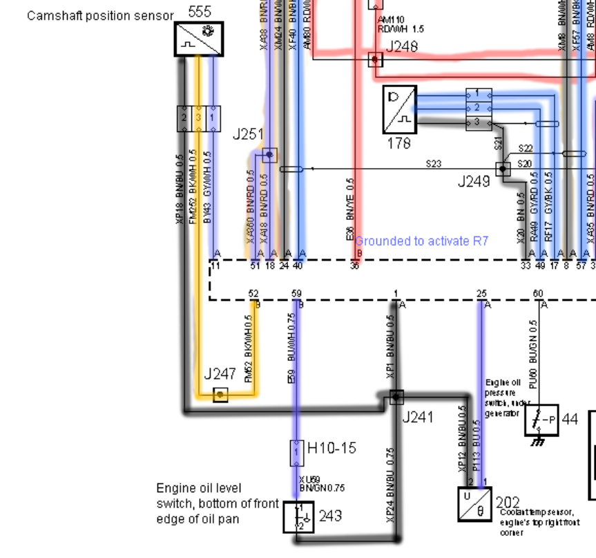
Any better ideas on how to proceed? I've attached the wiring diagram from the WIS. Black is constant ground, red is from the fuse box (constant battery voltage, however one red wire here is actually just the control of the relay R7), yellow is signal and purple is 5 V reference.
One idea I guess is to, with the sensor disconnected, backprobe the connector at the signal and reference wires and put alligator cables from there as well as from ground (just to not have too many pins in the connector) to the sensor pins, thus bypassing the connector...
Edit: After messing around with the terminal, trying to get it out of the connector to bypass it (unsuccessfully), it started working. I get a camshaft signal now when cranking, and it's a square wave and everything, but it's "ground" is at 170 mV compared to battery negative. I get similar readings on some parts of the engine, but not on the ECU strangely enough (the sensor gets its ground from the ECU after all). I tried hooking a jumper cable from battery negative to one part of the engine that showed 170 mV, and that solved the grounding kind of (it was at 0), but in turn the battery potential dropped because of this and it almost got so difficult that I even got a no-crank until I removed the jumper cable again! This would be a short-to-ground issue right? Would a 170 mV potential be enough to create a no-start?
Cheers!
Please Log in or Create an account to join the conversation.
- VegasJAK
-

- Offline
- Platinum Member
-

- Silencing the Parts Cannon
- Posts: 566
- Thank you received: 140
You could also use your test light as well. Again disconnecting the harness from the ECM and sensor, connect the test light to battery positive, then touch one end of the ground wire. If the test light glows, you have a short.
Remember, sensors share grounds. Unplug each sensor one at a time and see if the Ohm reading drops. If it does you just found the bad sensor causing the ground issue. If not you will have to look for contact points along with wire and isolate points until you find where the wire is grounding.
"an open mind let's knowledge flow in and wisdom flow out for a man who has neither never listens to those who have both".
Please Log in or Create an account to join the conversation.
- Vaering
-
Topic Author
- Offline
- New Member
-
- Posts: 4
- Thank you received: 0
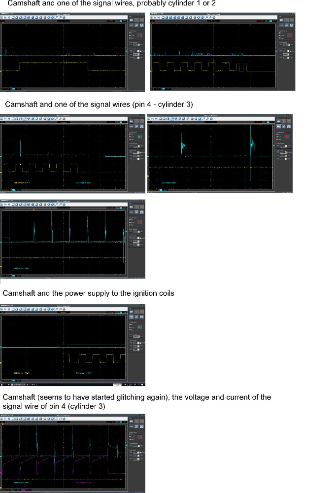
I've done a lot of tests now on the ignition signal wires, it seems the ECU is constantly just grounding (to allow current to load up the coil) without actually triggering. Instead I still get a firing line from just spontaneous ignition from the current being charged in the coil, even though the ECU doesn't set the voltage back to 12, is that possible? At the bottom you can see my measurement of the current and voltage on one of the ignition control wires, indeed the current just immediately starts to go up, so that must be it - the ECU never signals to stop charging the coil, right? Or is there a short to ground in the coil wire or pack that only shows itself with enough current load?
I've attached an image of all tests, please check it out!
Edit: It wasn't so easy to zoom here, so here's an external image host: pasteboard.co/IHJxKPC.jpg
Also, here's the ignition system description from the WIS: pasteboard.co/IHJRwyD.png
And the WIS wiring diagrams for the ECU and ignition system with my annotations: pasteboard.co/IHJUFyB.jpg
I tried now with the cam sensor disconnected. The probe that was earlier on its signal wire is now on the engine, as you can see the engine ground looks pretty messed up: pasteboard.co/IHKMcLU.png
Please Log in or Create an account to join the conversation.
- Vaering
-
Topic Author
- Offline
- New Member
-
- Posts: 4
- Thank you received: 0
I also tried putting the yellow to the disconnected cam sensor connector ground, and voltage/current to another cylinder here (the last pin): pasteboard.co/IHKTrTq.png This time it was in "Normal" mode which means that what you're seeing here is the last part before I turn the ignition off. Weird how the last voltage waveform looks like a decent spark with the ECU pulling up to voltage....
Here's another one, but in the beginning of the cranking. Voltage isn't pulled to ground by the ECU at first, then it grounds it and current flows and the ground stays there: pasteboard.co/IHKXqE1.png Average ground (yellow) is really bad at 500 mV and oscillating like crazy (here it's battery negative to the disconnected cam sensor ground pin). Tried this on the ECU cover instead of the cam connector pin as well and it looked the same: pasteboard.co/IHLevVl.png
And with a jumper from battery negative to ECU cover, improved it a little bit: pasteboard.co/IHLe2rY.png
Also tried putting the jumper instead from the lower engine block (where there's an oxygen sensor in the middle) to the ECU, looks the same as well, or actually just a tad worse than jumping battery to ECU.
Please Log in or Create an account to join the conversation.
- VegasJAK
-
- Offline
- Platinum Member
-
- Silencing the Parts Cannon
- Posts: 566
- Thank you received: 140
You cannot check the ground voltage while cranking as you will get starter voltage spikes. It can only be checked KOEO or engine running.
Engines run mostly on crank sensor and can run with a bad cam sensor. The crank sensor is on a separate circuit so check it as well.
"an open mind let's knowledge flow in and wisdom flow out for a man who has neither never listens to those who have both".
Please Log in or Create an account to join the conversation.
- Vaering
-
Topic Author
- Offline
- New Member
-
- Posts: 4
- Thank you received: 0
Yeah, I always get those when disconnected, so the signals from the ECU are fine for the cam sensor.scannerjohn wrote: your cam sensor is a Hall Effect pull down design. You should have 5v on both signal and reference wires with the sensor unplugged. The ground wire should have at or less than .1volts (100mv) plugged in. The Hall grounds pulling the signal down from 5v to 0v then back to 5v so the PCM sees a signal of 0-5volts in a square wave. I said before 170mv on the ground seems high, but if its running its at high limit.
You cannot check the ground voltage while cranking as you will get starter voltage spikes. It can only be checked KOEO or engine running.
Engines run mostly on crank sensor and can run with a bad cam sensor. The crank sensor is on a separate circuit so check it as well.
Oh, I suppose the ground is maybe not the concern then.
I don't think the crank sensor could be it though right, since I'm getting an rpm signal? It's incredibly difficult to get to and is covered in oil since it's under the oil filter. Difficult to backprobe it since it's just one solid wire in a harness shared with the oil tank sensor until the very last few cm before the sensor itself. I'd probably have to lift the car up...
Something that does look very wrong though are the ignition control results I got. I shouldn't get constant ground (apart from the spike signalling ignition or something every 3 ms(!)) on the ignition coil control wires right? And as a result, the current on the same control wires are just never-ending current ramps right after each other without any break, at that same frequency - every 3 ms, so since each crankshaft revolution is 0.3 s (200 rpm), there seems to be 100 ignitions each revolution which is of course insane). Something causes the control wire to not get its 12 V back to disallow current passing through it until it's time for another ignition. I guess it could be a bad ECM, or as we talked about earlier, a short to ground that prevents the coil from getting enough current to make the ECM pull the voltage back up for ignition (according to the WIS which says it "checks" the current, it only raises the voltage back up when there's enough current I think)? Have you seen ignition waveforms like these before? I can't find anything on the web that looks quite like my case, other than that the current waveforms look like a shorted coil (steep beginning of ramp).
It's also a bit interesting that the ignition control wires seem to show slightly different results, especially different results on the same wire after wiggling it (third and fourth pictures in the link here). I also tried measuring battery voltage at the bottom but AFAIK the relative compression looks good (you can see the scaling at the bottom left, so as before, yellow is 500 mA/grid, blue is 20 V and purple is 5 A): pasteboard.co/IHN4Aye.jpg
Yes, the battery might have been a bit weak there during the relative compression test, getting below 10 V sometimes, but it was at the end of a long day of just cranking and testing all kinds of stuff
")
So yeah, I think the best idea now is to do resistance tests for short to ground in the wires like you said earlier. Is there anything in these ignition control plots I've attached that says anything about short to ground or anything? Why would I get these spikes at such incredibly fast frequencies? Is there some kind of ignition going on even though the ECU doesn't raise the voltage to stop the current?
Edit: I'm currently doing resistance tests between ground and ignition control wires after having the battery removed overnight (still is removed) and getting the ECU connector off, while messing around with the cable. No signs of short to ground there anyway yet - at 20MOhm scale it's always "O.L.", but at 200MOhm scale I get a reading at 100 even on the cables themselves so that's probably too high of a setting.
I did continuity from each ignition control wire to its two ECU contacts also while I was at it, even though I know it probably won't show anything without any load, but I figured it'd maybe show discontinuity when messing with the wires to indicate an open wire. I don't think this could possibly be open wiring issue, because then I don't think I'd get ground at all on the control wires, but who knows...
Edit: I think I may have found something interesting... Fuse 4 delivers +15 ("ON"/"ST") from relay 11 and then goes to the battery disconnect switch (I don't think I have that), power steering unit (which is lacking its ground by the way), ECU and the coil pack (the power signal). I think I found a short to ground here, between the coil pack power signal wire and ground. I tried ECU ground, battery terminal, and some other places to verify and got the same results. I have the ECU A-cable disconnected (which includes the coil pack) and also the ignition cable disconnected from the coil pack. I only got 2 kOhm, or 4 kOhm when fuse 4 was removed. The relay should be off when ignition's not in "ON" or "ST" (I don't even have a battery now), so I don't see how this could be anything but a short, right?
Here's the diagram: pasteboard.co/IHUAYGz.png
And I also checked if the ECU path from fuse 4 is to the unplugged A-connector but it's the B-connector, which is plugged in still: pasteboard.co/IHUEiyd.png
The crimp J232 goes to the control of relay 8 as well, and back to the B-connector, so I guess the ECU controls R8 that way by grounding it: pasteboard.co/IHULniS.jpg
Took a bit of effort but I removed the B-connector as well on the ECU (so both are off now) and now it's just 1243 ohms from the power signal wire on the disconnected coil pack connector to ground (tried engine block, battery negative terminal etc...). Even when I remove R8 - the crimp J232 goes to the control of relay 8 as well, and back to the B-connector, so I guess the ECU controls R8 that way by grounding it: pasteboard.co/IHULniS.jpg. That could've explained the grounding if the ECU was messed up and grounded it constantly, but both connectors are off now as well as the relay...
2019-11-23:
Did more tests today, and made sure cam signal at least worked now. Here's cylinder 2 current and voltage as well as cam signal and ground for the cam is ECU ground and battery negative for the cylinder: pasteboard.co/II16v1O.png
With the cam signal, at least the ECU seems to do its work. But I still get some kind of misfire, maybe the coil is toast after all these cranking tests with constant ground, or maybe the timing is off...
More tests coming up, including timing (tried to use current clamp over both crank wires but it didn't work, so I'll have to backprobe somehow I think)
Please Log in or Create an account to join the conversation.
- Calan1964
-
- Offline
- New Member
-
- Posts: 1
- Thank you received: 0
Please Log in or Create an account to join the conversation.