Civic elusive misfire
- hoddy2000
-
 Topic Author
- Offline
- New Member
-

- Posts: 14
- Thank you received: 2
misfire mainly (95%) occuring on cyl 3 but 5% cyl 1 only under these conditions:
1900 rpm, 4th or 5th gear with light throttle application.
Can't reproduce at idle or 1900 rpm in the garage.
Misfire disappears under more throttle application.
spark, coil, injector have been moved to another cylinder. misfire remains on cyl 3.
fuel pump and filter changed, injectors cleaned
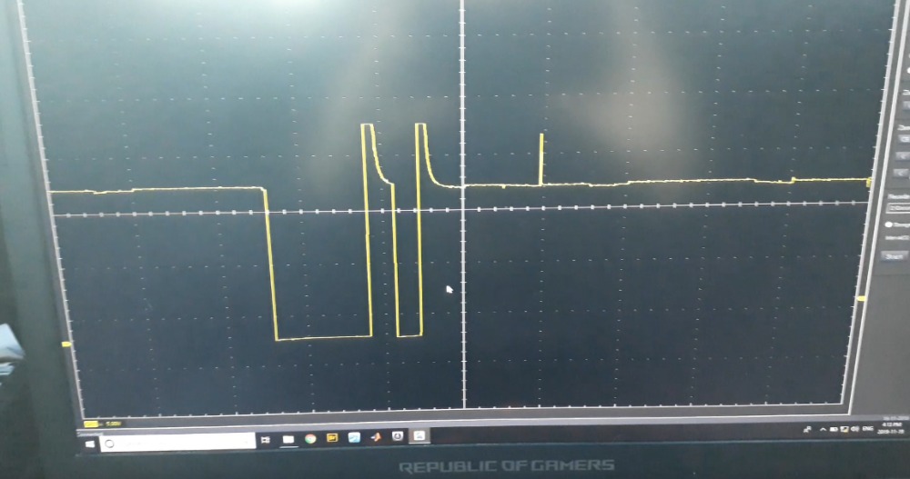
I have a video of the injector control wire which I'll attach. I don't have the experience to know what I'm looking at though. Any help?
also see the video of it here
Please Log in or Create an account to join the conversation.
- Noah
-

- Offline
- Moderator
-

- Posts: 5028
- Thank you received: 1119
I don't remember how to access the e-book, so a picture of the hard copy will have to do:
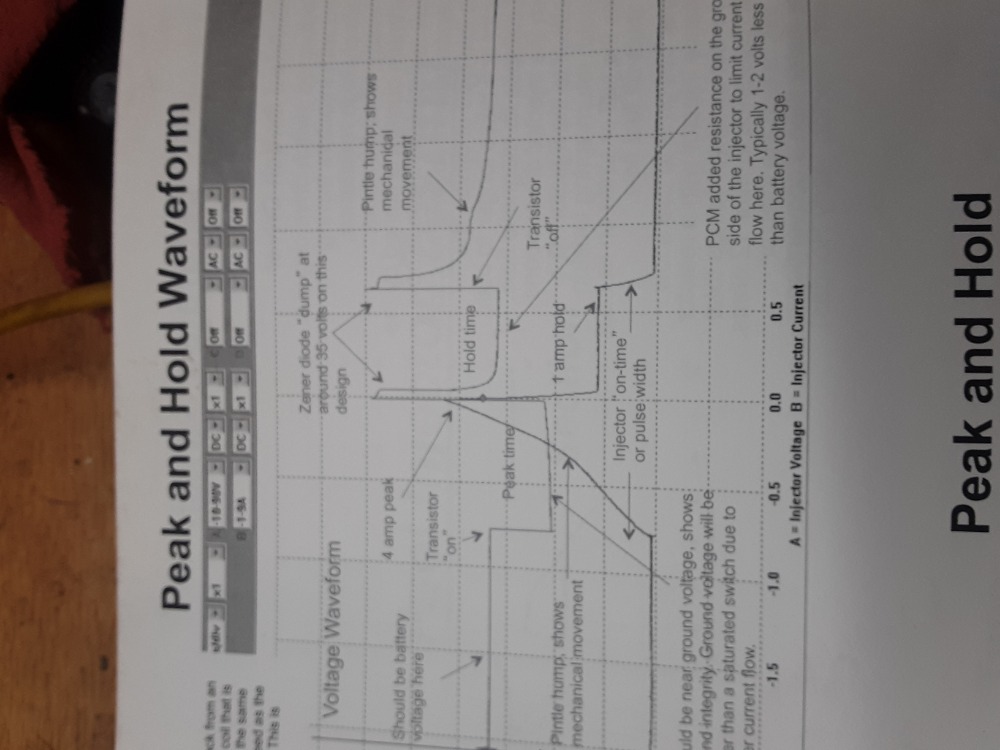
Did you repeat that test on a cylinder that is not reporting misfires?
Yours looks like it's being pulled fully to ground for the second half of the pattern while the examine does not.
Please Log in or Create an account to join the conversation.
- hoddy2000
-
Topic Author
- Offline
- New Member
-
- Posts: 14
- Thank you received: 2
Please Log in or Create an account to join the conversation.
- Noah
-
- Offline
- Moderator
-
- Posts: 5028
- Thank you received: 1119
Please Log in or Create an account to join the conversation.
- hoddy2000
-
Topic Author
- Offline
- New Member
-
- Posts: 14
- Thank you received: 2
Please Log in or Create an account to join the conversation.
- hoddy2000
-
Topic Author
- Offline
- New Member
-
- Posts: 14
- Thank you received: 2
video of Cyl3 and Cyl4 injector control wires.
Misfire condition appears only on Cyl3 at about 1900 rpm and light throttle application. At idle it disappears. At more open throttle it disappears. Can anyone help identify the cause of this weird waveform?
Please Log in or Create an account to join the conversation.
- Noah
-
- Offline
- Moderator
-
- Posts: 5028
- Thank you received: 1119
I would scope the cam and crank sensors during that event.
I don't know if the PCM could "double tap" that injector on purpose if it was pulling too much amperage, but I would also current ramp that injector at idle and during that event and compare that to a known good cylinder under the same conditions.
Please Log in or Create an account to join the conversation.
- Landroverman1958
-
- Offline
- Premium Member
-

- Posts: 93
- Thank you received: 17
Please Log in or Create an account to join the conversation.
- hoddy2000
-
Topic Author
- Offline
- New Member
-
- Posts: 14
- Thank you received: 2
Please Log in or Create an account to join the conversation.
- hoddy2000
-
Topic Author
- Offline
- New Member
-
- Posts: 14
- Thank you received: 2
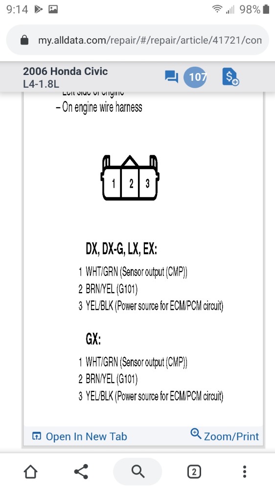
Camshaft Position Sensor on CH1 in YELLOW (middle)
Crankshaft Position Sensor on CH2 in green/blue (top)
Cyl3 Injector Control in Magenta (bottom)What could be the cause of this spike in voltage in time with the cyl3 firing? And there is a smaller spike at what I assume from the CKP waveform is TDC. Keep in mind I get misfires 90-95% on cyl 3 and the rest on Cyl1. Any thoughts on what could cause this?
Please Log in or Create an account to join the conversation.
- Dtnel
-

- Offline
- Platinum Member
-

- Posts: 452
- Thank you received: 67
I could look the information up later today if so. LEt me know. @ The thread poster pm me the vin and I can see what I can find. Can't send diagrams though as that's a sketchy area I won't venture into. If I look it up and give you the color or I wonder if Paul is ok if I took a picture of the pinout with my phone and post the picture as I know as him being a content creator that's a hot button topic plus I don't know his position on it.
I've seen him use diagrams in his videos but I think that falls under a different area. If someone else knows otherwise please correct me.
Sent from my SM-N975U1 using Tapatalk
Please Log in or Create an account to join the conversation.
- hoddy2000
-
Topic Author
- Offline
- New Member
-
- Posts: 14
- Thank you received: 2
It's a 3 wire sensor. Signal to the ECU is white/green. The ground wire seems good I checked voltage and resistance. the other wire YEL/BLK is from the Main relay. I capture battery voltage there. Maybe it should be 5 volts I don't know.
Please Log in or Create an account to join the conversation.
- Andy.MacFadyen
-

- Offline
- Moderator
-
- Posts: 3357
- Thank you received: 1037
" We're trying to plug a hole in the universe, what are you doing ?. "
(Walter Bishop Fringe TV show)
Please Log in or Create an account to join the conversation.
- hoddy2000
-
Topic Author
- Offline
- New Member
-
- Posts: 14
- Thank you received: 2
Please Log in or Create an account to join the conversation.
- Noah
-
- Offline
- Moderator
-
- Posts: 5028
- Thank you received: 1119
I'm thinking green is cam, pink is cyl 3 ignition and yellow is crank? It doesn't really look like a crank signal though? Sorry for the confusion on my end.
Also sorry for not getting back sooner. Life and work and what not...
There is a repeating double synch in the green trace, I don't have reference material in front of me at the moment, but from what I can recall of looking it up the other day I think the cam sync pulse was just a different sized pulse. I'll look it up again tomorrow and get back to you.
Any work done on the engine recently, or did this just come out of left field?
If you have the time and ambition it would cool to see if that double pulse in what I think is the cam signal corresponds to the double injector pulse.
I think the spike is just a kind of inductive resonance from the coil firing. Not really there, so to speak.
I also think the misfires on cylinder 1 really aren't there. It's not uncommon for me to see a companion cylinder count false misfires in much lower amounts during a single cylinder misfire.
Please Log in or Create an account to join the conversation.
- hoddy2000
-
Topic Author
- Offline
- New Member
-
- Posts: 14
- Thank you received: 2
Camshaft Position Sensor on CH1 in YELLOW (middle)
Crankshaft Position Sensor on CH2 in green/blue (top)
Cyl3 Injector Control in Magenta (bottom).
It's the yellow signal- the camshaft sensor - that looks out to lunch to me. I think it should be a square wave but I have no reference material to check it against.
I think the double sync in the green is a marker for tdc, but again I have no reference for that. It's not aligned with cyl3 in magenta either way.
If I had a spare cam sensor I'd swap it for that. Is there a test you can do to see if the cam sensor is functioning as designed? It's giving these weird pulses and then that giant pulse right in time with cyl 3 where the miss is usually happening. I wasn't driving during this last scope it's at idle.
Please Log in or Create an account to join the conversation.
- Noah
-
- Offline
- Moderator
-
- Posts: 5028
- Thank you received: 1119
The yellow trace certainly does not look like what the cam sensor should be producing.
It should be a square wave as you had mentioned.
As far as testing the sensor, I believe you said you tested and found power and ground at the sensor all ready.
That's good. If you're certain you were making good contact on the signal wire during that capture then there's something wrong there.
Before condemning the sensor, I would check the signal wire for a short to ground by disconnecting the sensor and the computer and then ohm the signal wire to ground. Looking for OL mohms.
I see the trace stays around 1-2v on the scope, so I don't think you'll find a short but I would check before replacing the sensor anyway.
You could also yank the end cover and check the tone generator for damage, can but given it location I don't think it would likely be damaged.
I would imagine that with what amounts to no cam sensor signal there would be a trouble code set...
Please Log in or Create an account to join the conversation.
- hoddy2000
-
Topic Author
- Offline
- New Member
-
- Posts: 14
- Thank you received: 2
1 - camshaft sensor
2 - crank sensor
3 - Cyl3 Injector Signal
4 - Cyl3 Ignition Coil (I'm not sure what this wire is called, but not batter voltage and not ground, it's a 3 wire.
Here's what I see. Nothing in any of the other channels. The others seems stable and that injector signal seems to come out of nowhere. So I think I'm getting good data to the ECU from CMP and CKP. Any other ideas? I haven't checked the current to the injector, but I'm not sure if there's a reason for that? ... Yeah, you told me to current ramp the injector at idle and during the event - i just re-read that so I will do that and post it.
Please Log in or Create an account to join the conversation.
- hoddy2000
-
Topic Author
- Offline
- New Member
-
- Posts: 14
- Thank you received: 2
Please Log in or Create an account to join the conversation.
- Noah
-
- Offline
- Moderator
-
- Posts: 5028
- Thank you received: 1119
I don't see any funny business with the cam signal while the PCM is double firing the injector.
Aside from Landroverman's advice about checking pin fittment, I don't have any ideas beyond changing the PCM.
Please Log in or Create an account to join the conversation.