2002 BMW 316i E46: Is the crankshaft sensor dead?
- motah33
-
 Topic Author
- Offline
- New Member
-

- Posts: 8
- Thank you received: 8
If I connect a multimeter between Pins 2 (negative lead) and 3 (positive lead), I measure about 7M ohms. Does that sound about right? Can measuring the resistance damage the sensor in any way? I read on a forum that it could. However, on my DMM, at 40Mohm setting, it barely produces a 1mV.
I measured the voltages on Pins 1, 2 and 3 on the connector (no sensor connected), with the ignition on, and got the following:
+11.8V between Pins 1 and 3
+10.8V between Pins 2 and 3
Pin 2 as the signal/reference pin is not +5V but close to +12V. When I turn the ignition off, all the pins show 0V.
I connected a crankshaft sensor to the car, brought a large spanner next to it and nothing happened to the voltage on Pin 2 i.e. the +10.8V stayed fixed. From what I read online, bringing a metal object next to the sensor should cause that voltage to drop to 0V. That could be pointing to a bad crankshaft sensor?
I was watching the 'Hall effect cam/crank sensor operation and testing Part 2 (an SD Premium video)' and about halfway through, with the section on the bypass test, I got the impression that the engine may respond differently if there are camshaft sensors on the car as well. I've got 2 camshaft sensors and 1 crankshaft sensor. I presume this doesn't affect the issue with the sensor itself but does that mean the ECM needs to see signals from the camshafts too before it starts to activate the fuel pump, injectors etc?
Is it possible to bench test a crankshaft sensor? Supply +12V to Pins 1 & 2, GND to Pin 3, bring a metal object close to the sensor, and the voltage on Pin 2 should be close to 0V?
Thanks
Please Log in or Create an account to join the conversation.
- jreardon
-
- Offline
- Platinum Member
-

- Posts: 521
- Thank you received: 198
"bringing a metal object next to the sensor should cause that voltage to drop to 0V. That could be pointing to a bad crankshaft sensor?"
Yes.
"does that mean the ECM needs to see signals from the camshafts too before it starts to activate the fuel pump, injectors etc?"
Maybe, it depends, that's why the bypass test is not 100% reliable across all car makes to work because some cars need both cam and crank to be timed correctly for a reaction. However in your case you could try cranking the engine while creating a low signal on the signal wire (incandescent test light to battery ground). Couple this with a crank sensor signal fixed high and a successful bypass test with engine cranking, and a successful computer reaction like an rpm signal in your scan tool, that maybe all the info you need to buy a new crank sensor.
Is it possible to bench test a crankshaft sensor?
Yes.
Please Log in or Create an account to join the conversation.
- motah33
-
Topic Author
- Offline
- New Member
-
- Posts: 8
- Thank you received: 8
I did try what was demonstrated in the video you linked to. At that time, I didn't know whether it was a 12V or 5V signal type, so I connected it up as shown in the video. When I found out it was a 12V type, I tried again but this time I used a single 12V supply: Pin 1 was 12V, Pin 2 was pulled up to 12V via a 2kohm resistor and Pin 3 went to GND. Again, it didn't work. I don't know if that's the right way to do it or if I need a separate 12V supply for Pin 2?
I do have another sensor that I can test with. The one I was using was I bought used and there was always the chance that it may not be working. The one I pulled off the car, I just discovered is fairly new as it was fitted about 4 years ago and it's a genuine BMW sensor.
I was reluctant to try any tests with it because I didn't want to damage it. I was trying to diagnose rough idling, stalling etc. I now know that there are vacuum leaks which I've been slowly fixing. The sensor removed from the car might be fine (the car starts ok) but I would like to do some sort of test on it to give me some more confidence - it's very difficult to remove because it requires the entire inlet manifold to be taken out before you can access it.
Is there any way to damage a sensor e.g. if you bench test it, for example, or by measuring its resistance? There was thing on one of the BMW forums that measuring its resistance would damage it. I thought it's too small a voltage/current from the DMM to any damage. What are you thoughts on that?
Even if a sensor passes some basic tests, is it possible that it's only working intermittently? Again, I read on a forum that either the sensor works or it doesn't - there is no in-between state.
Thanks
Please Log in or Create an account to join the conversation.
- jreardon
-
- Offline
- Platinum Member
-
- Posts: 521
- Thank you received: 198
When I found out it was a 12V type, I tried again but this time I used a single 12V supply: Pin 1 was 12V, Pin 2 was pulled up to 12V via a 2kohm resistor and Pin 3 went to GND.
I think you mean to say pin 2 was supplied 12v through a 2kohm resistor.
Even if a sensor passes some basic tests, is it possible that it's only working intermittently?
Yes. If it passes your bench test, that's no guarantee it would continue to work in the confines of a hot engine compartment.
I only have Chrysler videos to prove my points, same pull down design, only it uses 5v:
Failure during engine running (this sensor would have benched fine on a nice cool table):
Here's one that looks fine on the scope but the computer doesn't like it anyway lol, (junk aftermarket part):
Is there any way to damage a sensor e.g. if you bench test it, for example, or by measuring its resistance? There was thing on one of the BMW forums that measuring its resistance would damage it. I thought it's too small a voltage/current from the DMM to any damage. What are you thoughts on that?
I don't know. I have an auto-ranging DVOM that run off 2 AA batteries, I never measured for myself but I'm leaning towards the no effing way camp lol. I don't have another meter to measure the meter.
You can measure yourself if the current is over the threshold for specifications: www.newtis.info/tisv2/a/en/e46-316i-lim/XM3JZqD
"Maximum output current: 20 mA"
Now is that measuring current on the ground wire (total sensor current draw), or just the supply wire, or just the signal wire? I don't know.
May I ask what codes you're getting?
If the crankshaft sensor fails, the following behaviour is to be expected:
Fault entry in the engine control unit
Emergency operation with substitute value
This car model is not in my database so I can't look up codes. I know substituted values can't be in the obd2 global room in the scan tool, maybe you can see rpms missing in there?
Please Log in or Create an account to join the conversation.
- motah33
-
Topic Author
- Offline
- New Member
-
- Posts: 8
- Thank you received: 8
Yes, you're right, Pin 2 was supplied +12V via a 2kohm pull-up resistor.
Thanks for those links. So, the sensor can have intermittent problems. That's reassuring!
")
I did use a second DMM to measure the one I was using for resistance and the voltage varied from around +1mV at the 40Mohm setting to around +2V at the 400ohm setting. I only used the 40Mohm setting.
The car's idle was rough to say the least. It started fine every time. And if I left the engine idling, some time later, it will stall. On occasions, it wil stall when stationary at traffic lights. You won't even know it's stalled until you try to pull away - the engine cuts out very silently.
After much research on the BMW forums, the crankshaft sensor came up as likely culprit. I bought a used one, the one I've been testing with, from the user of a 318i in anticipation of having to change it when I got to that part of the job. The more I researched and learnt about vacuum leaks, I realised that this might be one of the main causes, if not the cause, of the rough idling and stalling.
I knew the car was leaking from two places which I've fixed: the sump (which I to replace all together, not just the gasket) and the engine's vacuum pump (seals needed replacing). I removed the inlet manifold because I needed to replace the CCV/Oil Seperator and associated hoses (one broke when removing it from the sump) - it's the only way to get access to it. I found quite a lot of oil in the inlet manifold/throttle housing.
Since the manifold was out, I could get access to the crankshaft sensor which is buried unlike the two camshaft sensors. I'll be replacing the gaskets for the inlet manold, the oil seals on the injectors, the gaskets on the oil filter housing and the valve cover. These are all know to leak. I managed to pick up some history on the car and discovered that all of these areas were marked for work.
This was my sister's car. I did drive it around 400 miles or so before I started working on it. I bought one of those Bluetooth OBD2 scanners. These were the codes that I read (this was before I started working on the car):
P1114 - Powertrain (Current Fault)
P0015 - Powertrain (Pending Fault): "B" Camshaft Position - Timing Over-Retarded (Bank 1)
P0015 - Powertrain (Pending Fault): "B" Camshaft Position "B" Circuit (Bank 1)
I haven't used the scanner since working on the car.
I read that with these types of scanners, you man not see a crankshaft sensor fault logged unless you use the kind of scanner that can interrogate the ECM deeper. With the above codes, is one of the camshaft sensors a problem too or is this all related to vacuum leaks, unaccounted for air in the system and subsequently wrong timing by the ECM? I didn't find anything wrong with the rubber boot on the MAF but I did find there was a problem with a thin plastic pipe that went to the MAF or air filter box - can't remember which.
As I mentioned before, the crankshaft sensor was changed about 4 years. I would imagine a fault was logged. It could be that the BMW sensor removed from the car is fine and it's all the other issues mentioned that need addressing first. The trouble is once you bolt everything up, you can't get access to this sensor which is why I was trying to get some confidence in this sensor before putting everything back. It might be easier just buying a new one!
One other thing I did find was oil in the crankshaft sensor when I removed it from the car. I'm pretty sure that I didn't get oil in there.
Please Log in or Create an account to join the conversation.
- Andy.MacFadyen
-

- Offline
- Moderator
-

- Posts: 3357
- Thank you received: 1037
" We're trying to plug a hole in the universe, what are you doing ?. "
(Walter Bishop Fringe TV show)
Please Log in or Create an account to join the conversation.
- Andy.MacFadyen
-
- Offline
- Moderator
-
- Posts: 3357
- Thank you received: 1037
" We're trying to plug a hole in the universe, what are you doing ?. "
(Walter Bishop Fringe TV show)
Please Log in or Create an account to join the conversation.
- motah33
-
Topic Author
- Offline
- New Member
-
- Posts: 8
- Thank you received: 8
The crankshaft sensor which was replaced about 4 years ago was a BMW original. I'm thinking that might be ok but I haven't tested it since removing it from the vehicle.
The mileage on this car is around 57K miles which is very little for a car this age.
The engine is a N42.
I'm also curious about those pending faults that the OBD2 scanner read.
Please Log in or Create an account to join the conversation.
- motah33
-
Topic Author
- Offline
- New Member
-
- Posts: 8
- Thank you received: 8
I'm using a single +12V supply. This goes to Pin 1 (+12V) and Pin 3 (GND). I then take a 2000 ohm resistor from the same +12V supply and apply it to the signal pin (Pin 2). This should simulate power to the electronics in the sensor and the signal wire pulled-up to +12V which is what the ECM would do. It's now down to the sensor to pull that signal wire to 0V when I bring a metal object to nexto to it. However, it stays at +12V. Am I supposed to have a separate +12V supply to the signal wire?

Please Log in or Create an account to join the conversation.
- motah33
-
Topic Author
- Offline
- New Member
-
- Posts: 8
- Thank you received: 8
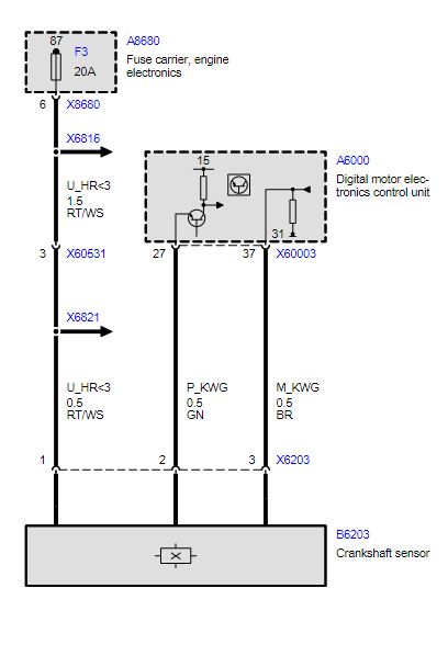
I just saw the wiring diagram for a N54 crankshaft sensor which is almost identical to the N42 one except Pin 2 is GND and Pin 3 is +5V. In the diagram I have for the N42, pins 2 and 3 are swapped.
Both the N42 and N54 engines show an A6000 DME control unit. The N54 shows a B6203a crankshaft sensor and the N42 shows a B6203 crankshaft sensor.
Please Log in or Create an account to join the conversation.
- jreardon
-
- Offline
- Platinum Member
-
- Posts: 521
- Thank you received: 198
motah33 wrote: Is it possible that pins 2 and 3 are wrong in the wiring diagram?
That wouldn't make any sense from the voltage measurements you took with the sensor unplugged.
Perhaps the description of the sensor is wrong and the increment wheel is the magnet, and the crank sensor responds to magnetic fields. Try a magnet off your fridge.
Please Log in or Create an account to join the conversation.
- motah33
-
Topic Author
- Offline
- New Member
-
- Posts: 8
- Thank you received: 8
I've tried it with magnets before and not got anything out of it.
I swapped pins 2 & 3 and I got a reaction. I have: Pin 1 = +12V, Pin 2 = GND, Pin 3 = +12V (signal) via ~2000 ohm resistor connected to same +12V supply as Pin 1. This is what the meters read:
No magnet near sensor:
Current being drawn from PSU: ~13.33mA
Signal voltage: ~178mV
Magnet near sensor:
Current being drawn from PSU: ~14.74mA
Signal voltage: varies to around ~775mV peak.
I also found that sometimes it would stick at ~775mV until I "unstuck" it by bringing a magnet next to it once again. It works the same way with the magnets and with a large spanner. I get the same voltage when looking at it on a scope: produces a square wave as you move something near it but the voltages are as above, not what I've seen in the videos.
This is what I don't understand: I went to re-check the crankshaft sensor's connector on the car and I'm still getting Pin 1 ~12V, Pin 2 ~10.8V and Pin 3 GND.
No idea what's going on here.
Please Log in or Create an account to join the conversation.
- motah33
-
Topic Author
- Offline
- New Member
-
- Posts: 8
- Thank you received: 8
I was using crocodile clips to connect to the pins on the sensor. They had boots on but it looks as they might have been touching at some point deep in the connector. I found some smaller ones, put insulation between them and it works - bring a magnet close to it and Pin 2 swings from +12V to 0 and back again!
When the voltage swing is normal, it takes 6.82mA (at +12V) but sometimes it sticks to 0V (takes 13.44mA). It might be just the way I move the magnet - it sticks to the sensor sometimes. But if I move the magnet close to it again, it works fine. Does this sound normal?
Could there be any damage to the sensor with the pins touching or when the pins were swapped?
This is from bench testing the sensor:
What I discovered is that the first time I apply power, the signal voltage is at +12V. When I move a spanner next to the sensor, the voltage on the signal pin stays at +12V. When I pull it away, it drops to 0V. Now, when I push the spanner towards the sensor, the voltage changes to +12V and when I pull it away, it goes back to 0V. This now repeats. It's just the first time, after power-up, that I get the unusual "sticking" effect. I realised that if try to move it past the sensor, side-to-side or some other pattern, it sometimes sticks at 0V but after a few more tries, it's fine. If I bring a spanner square on, wait for the voltage on the DMM to go to +12V, and then remove the spanner, the voltage then swings as expected. This works every time.
These are the results from trying it on the car:
The first time I connect the car battery to the car electrics, the voltage on the signal wire is +10.8V. After that, once I bring a spanner next to the sensor, the voltage drops to 0V. Thereafter, it works as above i.e. bring the spanner next to it and you get +10.8V and pull it away and you get 0V. Even if I switch the ignition off/on, it stays at 0V. It's only when I remove the leads from the battery and then re-apply, that I see the signal wire start at +10.8V.
Does this sound about right?
Please Log in or Create an account to join the conversation.